Model
8901B
Operation
IF
Frequency
FUNCTIONS
Special hnction
34
(IF
Frequency)
DESCRIPTION
The Modulation Analyzer makes tuned (down-converted, heterodyned) measurements on
its
RF input
signal using one of
two
IF
frequencies. Three combinations of tuning and
IF
selection are
used:
1.
When RF input signals less than
2.5
MHz are measured, the
RF
input signal passes directly
into
the
IF'
without down-conversion;
that
is,
the RF input frequency and the
IF
frequency are the
same.
(ked
measurements can be manually extended below
2.5
MHz. Refer
to
RF Bequency
Zbning
on page
3-115.)
2.
When RF input
signals
greater than
2.5
MHz, but less than
10
MHz are measured, the signal
is
down-converted
to
a
455
kHz
IF.
3.
When RF input signals greater than
10
MHz are measured, the signal
is
down-converted
to
a
1.5
MHz
IF.
(Note
that
special hction
3
can be used
to
select the
455
kHz
IF.
Refer
to
Filters, RF
and IF
on page
3-229.)
Special hnction
34.0
enables the Modulation Analyzer
to
measure and display the
IF
frequency for
the signal being measured.
PROCEDURE
To measure the
IF
frequency, key in
34.0
SPCL.
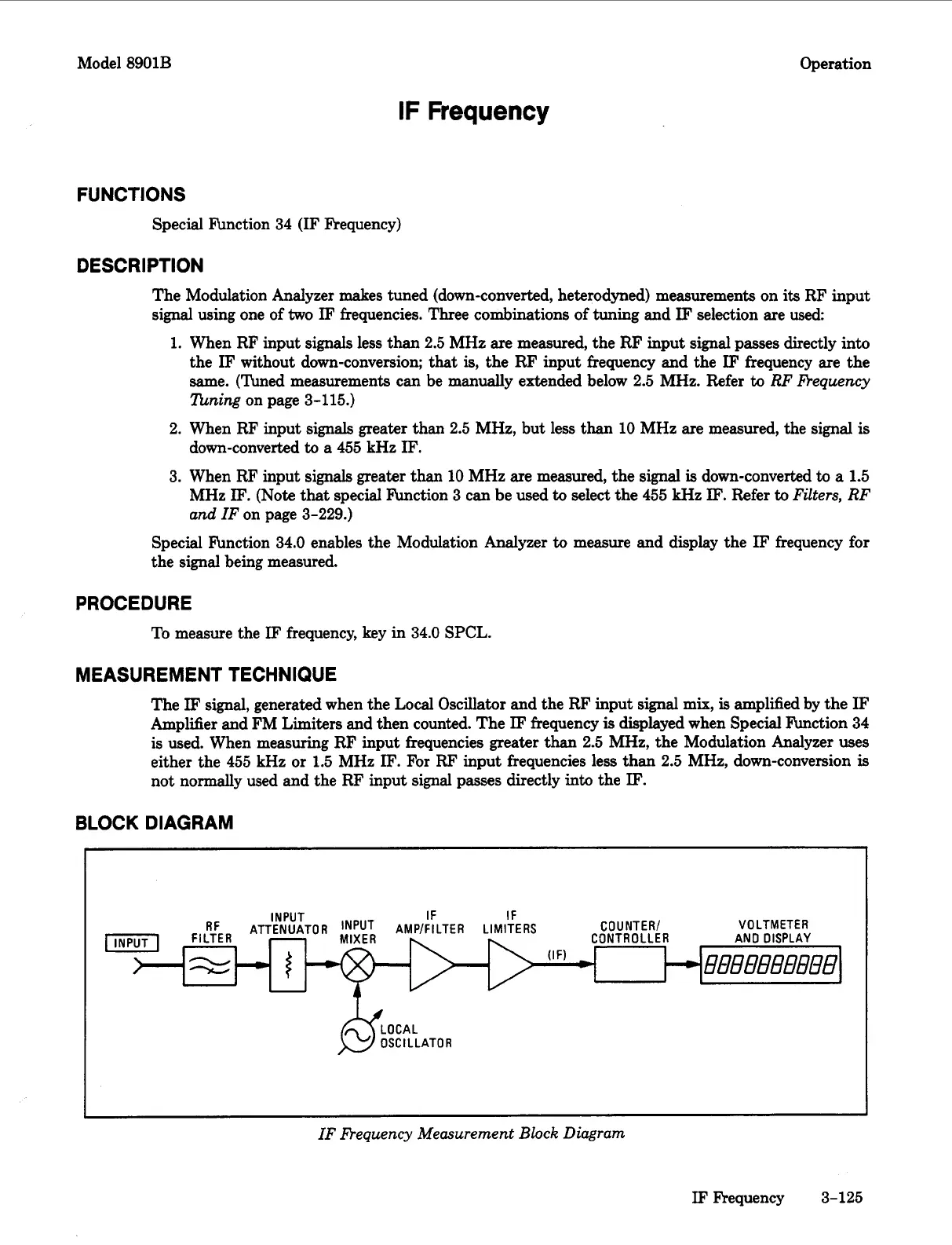
MEASUREMENT TECHNIQUE
The
IF
signal, generated when the Local Oscillator and the RF input
signal
mix,
is
amplified by the
IF
Amplifier and FM Limiters and then counted. The
IF
frequency
is
displayed when Special hction
34
is
used. When measuring
RF
input frequencies greater than
2.5
MHz, the Modulation Analyzer uses
either the
455
kHz or
1.5
MHz
IF.
For
RF
input frequencies less than
2.5
MHz, down-conversion
is
not normally used and the RF input signal
passes
directly
into
the
IF.
BLOCK DIAGRAM
VOLTMETER
IF
IF
Cn
U
NTE
R/
INPUT
RF
ATTCLIIIATnD
INPUT
AIID/CIITCD
I
InniTCoC
I
I
T-
U
.
I
IF Requency Measurement Block Diagram
IF
Frequency
3-125

 Loading...


