Operation Model
8901B
EXAMPLE
To measure the positive peak AM depth of
a
signal
in
a 50 Hz
to
15 kHz
demodulated signal bandwidth
LOCAL
(keystrokes)
(program
codes)
M1
D1
H1L2
Detector
Measurement
2l-X
Filters
HP-IB PROGRAM CODES
All
HP-IB codes for setting
a
limit or a specific display resolution for modulation-depth measurements
are provided in "Procedures".
AM
=
M1
SPCL
=
SP
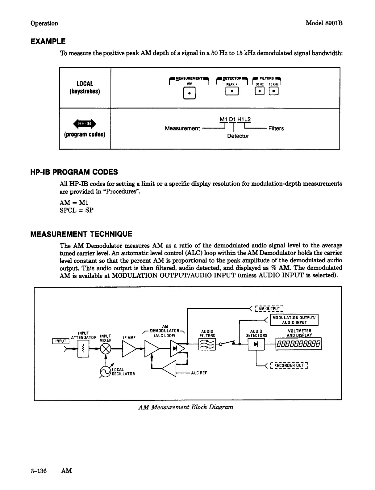
MEASUREMENT TECHNIQUE
The AM Demodulator measures AM as
a
ratio of the demodulated audio signal level
to
the average
tuned carrier level. An automatic level control (ALC) loop within the AM Demodulator holds the carrier
level constant
so
that
the percent
AM
is
proportional
to
the peak amplitude
of
the demodulated audio
output. This audio output
is
then filtered, audio detected, and displayed
as
'%I
AM. The demodulated
AM
is
available
at
MODULATION OUTPUT/AUDIO INPUT (unless AUDIO INPUT
is
selected).
I
AM
I
7
DEMODULATOR\
AUDIO
AUDIO VOLTMETER
(ALC LOOP)
FILTERS
DETECT0
RS
AN0 DISPLAY
INPUT
ATTENUATOR
IF
AMP
\'NPUTI
-
L
I
AM Measurement
Block
Diagram
3-136
AM

 Loading...


