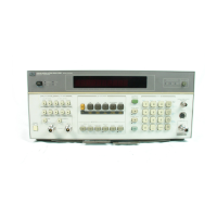
Model
8901B
General Information
LO
Circuitry
The
LO
drives the high-level port of the Input Mixer and
is
one of several inputs
to
the Counter. The
LO
has
four main modes of operation:
a
tuning
to
the frequency required to down-convert
a
signal whose frequency
is
entered from the
keyboard (manual tune mode),
a
automatically searching for an input signal, then tuning the LO
to
the frequency required
to
down-convert the signal (automatic tune mode),
a
automatically searching for an input signal, then configuring the
LO
in
a feedback loop that
automatically tracks the signal (automatic tune track mode), and
a
tuning
to
the frequency required
to
down-convert
a
signal whose frequency
is
entered from the
keyboard, then configuring the LO in a feedback loop
that
automatically tracks the input signal
(manual tune track mode).
The manual tune track mode
is
useful when
it
is
desired to follow an unstable signal in the presence
of other signals. The non-track modes are used when the
LO
noise (residual FM) must be minimized.
IF
Circuitry
The gain of the
IF
Amplifier
is
fixed. The
IF
Filters determine the frequency response of the
IF.
When
the
1.5
MHz
IF
is
selected, the
IF
filter consists of
a
150
kHz
to
2.5
MHz bandpass filter (with a
nominal center frequency
of
1.5
MHz). When the
455
kHz
IF
is
selected, the
IF
filter
is
the Wide
455
kHz Bandpass Filter (with a bandwidth of
200
kHz).
In instruments with Option Series
030,
the
IF
signal
is
further processed by the Channel Filters (which
also include
a
precision, variable-gain amplifier) and detected by the
IF
RMS Detector. The Channel
Filters set the
IF
bandwidth and gain for the Selective Power measurement. The measurement
is
made
by entering a series of Special Functions which establish
an
IF
reference in the center of the Channel
Filter, then allow the relative
IF
level
to
be displayed
as
the
IF
frequency
is
detuned
by
a
pre-determined
offset.
Audio Circuitry
The modulation on the
IF
is demodulated by either the AM or the FM Demodulator. Phase modulation
is
recovered
by
integrating the demodulated FM in the Audio
Filters
and Gain Control circuitry.
The demodulated signal
is
amplified and filtered in the Audio
Filters
and Gain Control circuitry. The
filters
are
selected from the front panel, and for FM, the filtering may also include de-emphasis. The
processed signal
is
passed
to
the front-panel MODULATION OUTPUT/AUDIO INPUT connector
and the voltmeter.
The audio signal from the Audio Filters and Gain Control
is
converted
to
a dc voltage by the Audio
Peak Detector, the Audio Average Detector or the Audio RMS detector. The Audio Average and RMS
Detectors are used primarily for measuring noise. The output from the detectors is routed into the
Voltage-to-Time Converter.
The Voltage-to-Time Converter within the voltmeter converts the dc input into a time interyal. During
the interval, the 10 MHz Time Base Reference
is
counted by the Counter, and the resultant count
represents the dc voltage. Other inputs
to
the voltmeter, which are not shown, include outputs from
an audio level detector and the AM calibrator.
The Distortion Analyzer measures the distortion of either the internal demodulated signal or an audio
signal applied externally
to
the MODULATION OUTPUT/AUDIO INPUT connector. The frequency
of
the input signal must be either
1
kHz or
400
Hz. The distortion on the signal
is
determined by
measuring the amplitude of the signal before and after a notch filter that
is
set
to
1
kHz
or
400
Hz.
The
two
ac signals are converted
to
dc by a the Audio RMS Detector and then measured by the voltmeter.
Distortion
is
computed
as
the ratio of the voltage out of the notch filter
to
the voltage into the filter.
(The Audio RMS Detector can also be used
to
measure the demodulated AM, FM,
or
OM internally
or the ac level of an external audio signal applied to the MODULATION OUTPUT/AUDIO INPUT
connector.)
1-11

 Loading...