General Information Model 8901B
The frequency of the audio signal at the MODULATION OUTPUT/AUDIO INPUT connector,
whether internal
or
external,
is
measured by a reciprocal-type Audio Counter. In the Audio Counter,
the input signal
is
used
to
gate the 10 MHz Time Base Reference into the main Counter. (This gating
function is
also
used by the Voltage-to-Time Converter.) The number of time base pulses received
during the count is read by the Controller which computes and displays the signal frequency.
The AM and FM Calibrators provide a nominal 10.1 MHz signal with
a
precisely known amount of
AM
or
FM. When this
signal
is
applied
to
the instrument’s RF INPUT connector (either directly
or
via the Sensor Module), the modulation is measured and the calibration factor of the AM
or
FM
Demodulator
is
computed and displayed. Related front-panel functions are automatically set for proper
demodulation of the calibrator signal.
P
(a)
BASEBAND SIGNAL
1.5
1
.o
0.5
0
(b)
AMPLITUDE MODULATED CARRIER
I
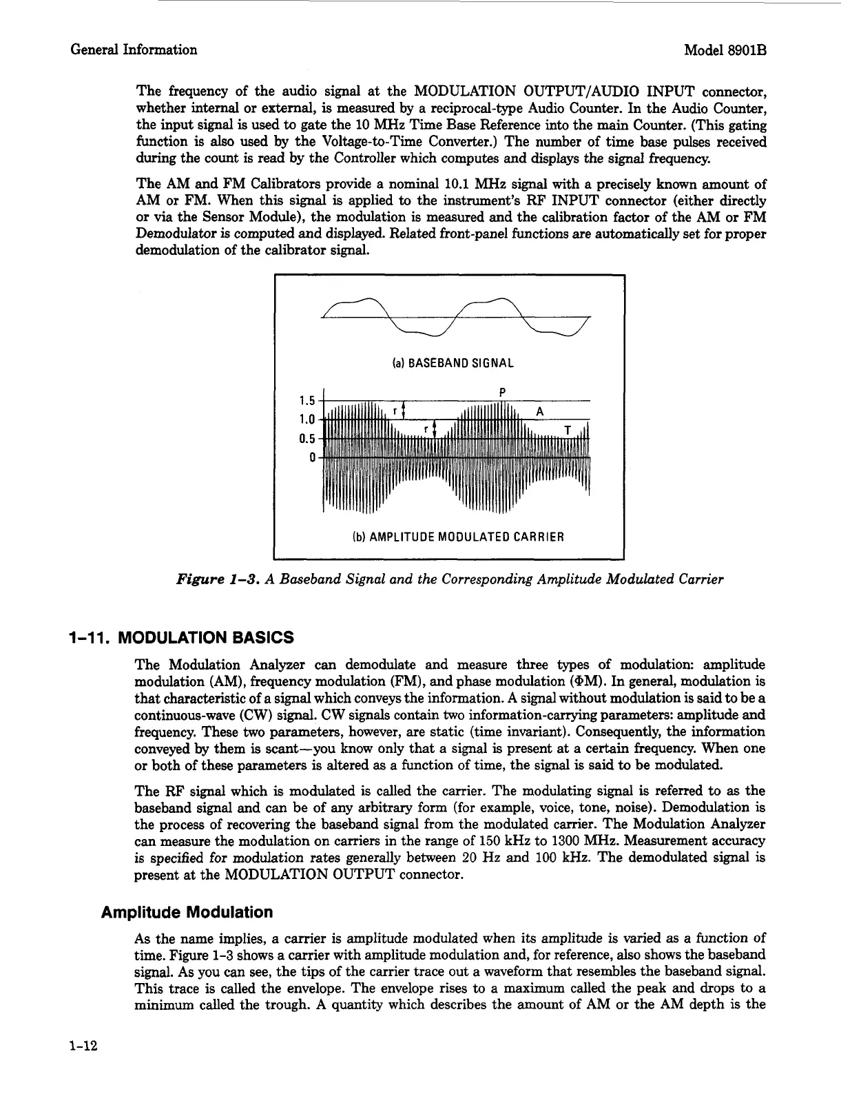
Figure
1-3.
A Baseband Signal and the Corresponding Amplitude Modulated Carrier
1-1
1.
MODULATION
BASICS
The Modulation Analyzer can demodulate and measure three types of modulation: amplitude
modulation (AM), frequency modulation (FM), and phase modulation (@M). In general, modulation is
that
characteristic of a signal which conveys the information.
A
signal without modulation
is
said to be
a
continuous-wave (CW)
signal.
CW signals contain
two
information-carrying parameters: amplitude and
frequency. These
two
parameters, however, are static (time invariant). Consequently, the information
conveyed
by
them
is
scant-you know only that a signal
is
present at a certain frequency. When one
or
both of these parameters
is
altered as a function of time, the signal
is
said
to
be modulated.
The RF signal which
is
modulated is called the carrier. The modulating signal
is
referred to
as
the
baseband signal and can be of any arbitrary form (for example, voice, tone, noise). Demodulation
is
the process of recovering the baseband signal from the modulated carrier. The Modulation Analyzer
can measure the modulation on carriers in the range of
150
kHz to 1300 MHz. Measurement accuracy
is specified
for
modulation
rates
generally between
20
Hz
and
100
kHz.
The demodulated signal
is
present
at
the MODULATION OUTPUT connector.
Amplitude Modulation
As
the name implies,
a
carrier is amplitude modulated when its amplitude
is
varied
as
a function of
time. Figure 1-3 shows a carrier with amplitude modulation and, for reference, also shows the baseband
signal.
As
you can see, the tips of the carrier trace out a waveform that resembles the baseband signal.
This trace
is
called the envelope. The envelope rises to a maximum called the peak and drops
to
a
minimum called the trough.
A
quantity which describes the amount of AM
or
the AM depth
is
the
1-12