Operation Model 8901B
The following table lists the different measurement range limits
that
can be selected with Special
F’unction
2:
Program Code
2.0SP
2.4SP
2.4SP
2.1 SP
2.2SP
2.3SP
Special
Function
Code
Detector
Selected
Modulation
Range
Peak-. rad.
dev.)
MODULATION
OUTPUT
Sensitivity
(mVac/radian)
Display
Resolution
(radians)
Automatic Selection
0.0001
10
0.001 1
0.001
1
0.01 0.1
0.1 0.01
Automatic Selection
2.0 SPCL
10.4
2.4 SPCL
Pk,
Avg
2.4 SPCL
54
540
Pk,
Avg, RMS
2.1 SPCL
Pk,
Avg, RMS
2.2 SPCL
1400
Pk,
Avg, RMS
2.3 SPCL
To filter the demodulated signal, select the appropriate
filter
keys. (Refer
to
Audio
Filters
on page 3-179
for more information about filters.)
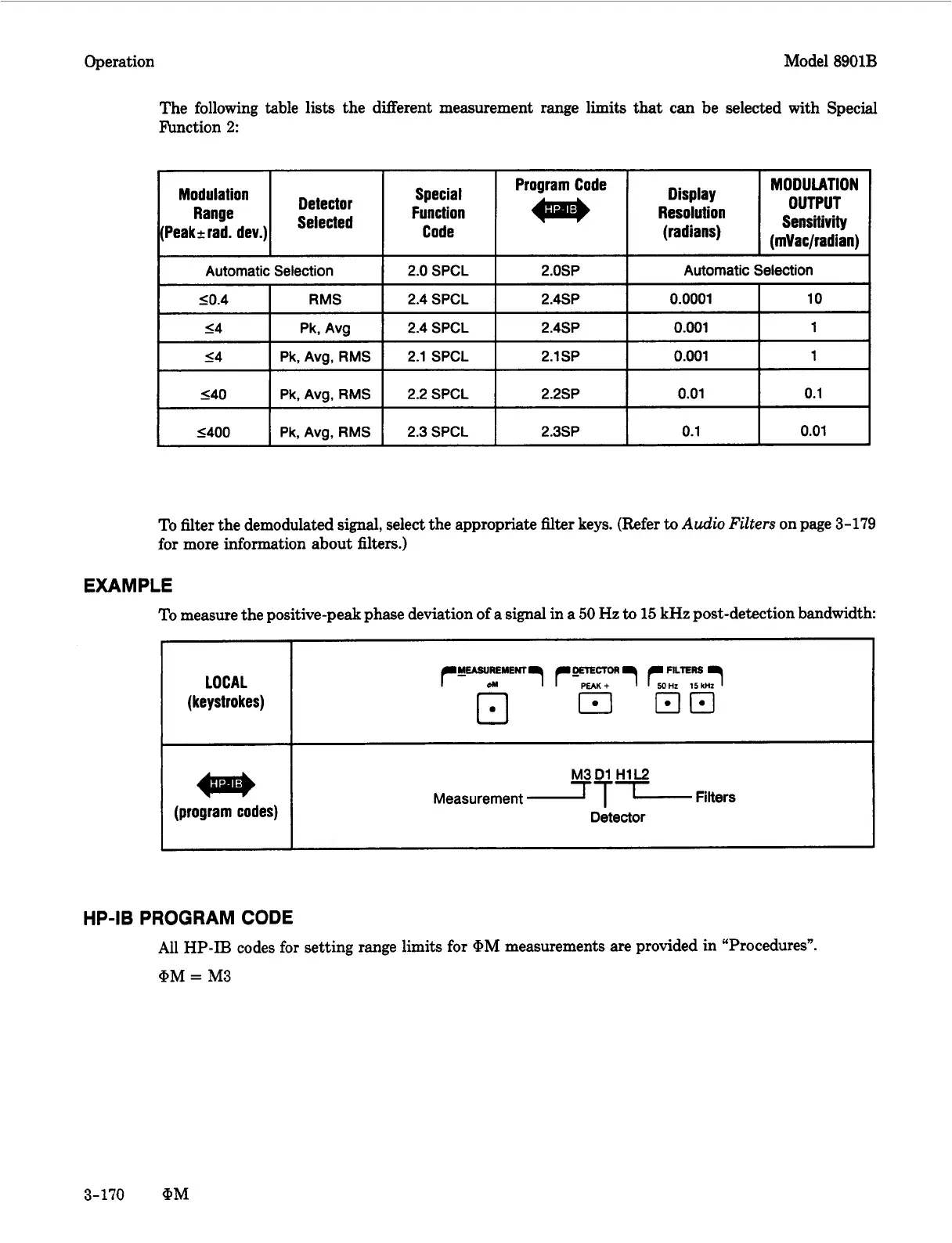
EXAMPLE
To
measure the positive-peak phase deviation of a signal in a
50
Hz
to
15
kHz
post-detection bandwidth
(program codes)
M3D1
H1L2
Measurement
LTL
Filters
Detector
HP-I6 PROGRAM
CODE
All
HP-IB
codes for setting range limits for @M measurements are provided in “Procedures”.
@M
=
M3
3-170
@M

 Loading...


