Model 8901B Operation
MEASUREMENT TECHNIQUE
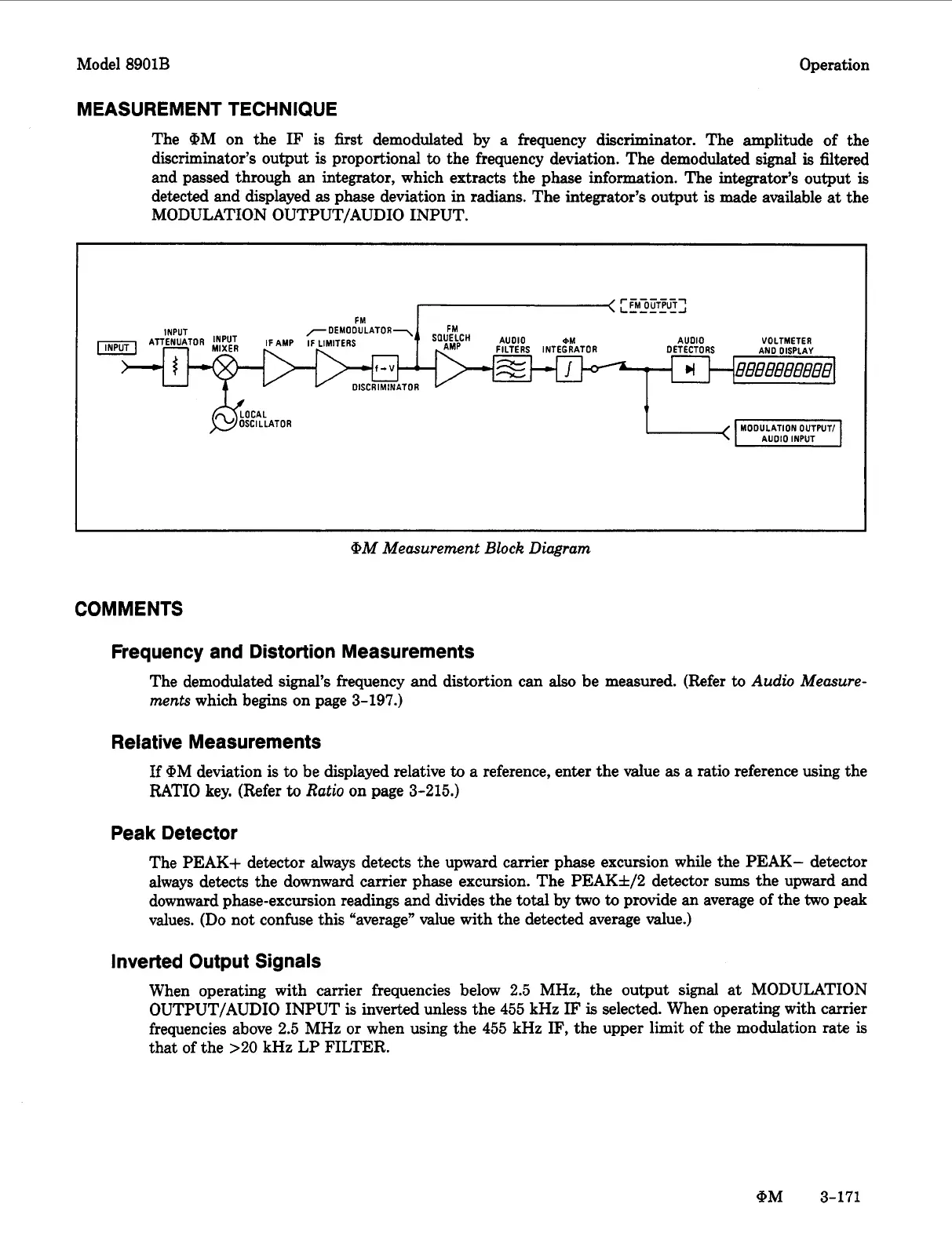
The
OM
on the
IF
is first demodulated
by
a frequency discriminator. The amplitude of the
discriminator’s output
is
proportional
to
the frequency deviation. The demodulated
signal
is
filtered
and passed through an integrator, which extracts the phase information. The integrator’s output
is
detected and displayed
as
phase deviation in radians. The integrator’s output
is
made available
at
the
MODULATION OUTPUT/AUDIO INPUT.
[-<
[
~M~L~T~LIT~
FM
-DEMODULATOR7
FM
VOLTMETER
AND DISPLAY
AUDIO
DETECT0
RS
INPUT
I
OM Measurement
Block
Diagram
COMMENTS
Frequency and Distortion Measurements
The demodulated signal’s frequency and distortion can
also
be measured. (Refer
to
Audio
Measure-
ments
which begins on page 3-197.)
Relative Measurements
If
@M deviation
is
to be displayed relative
to
a
reference, enter the value
as
a ratio reference using the
RATIO key. (Refer
to
Ratio
on page 3-215.)
Peak Detector
The PEAK+ detector always detects the upward carrier phase excursion while the PEAK- detector
always detects the downward carrier phase excursion. The PEAK*/2 detector sums the upward and
downward phase-excursion readings and divides the
total
by
two
to
provide an average of the
two
peak
values. (Do not confuse this “average” value with the detected average value.)
Inverted Output Signals
When operating with carrier frequencies below 2.5 MHz, the output signal at MODULATION
OUTPUT/AUDIO INPUT
is
inverted unless the 455 kHz
IF
is
selected. When operating with carrier
frequencies above 2.5 MHz or when using the 455 kHz IF, the upper limit of the modulation rate
is
that of the
>20
kHz LP FILTER.
(PM 3-171

 Loading...


