Model 8901B General Information
I
I
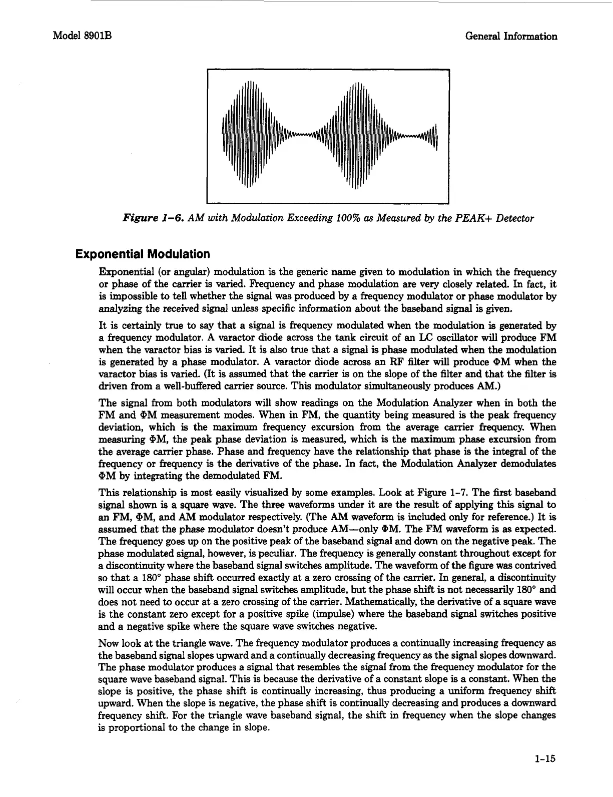
Figure
1-6.
AM with Modulation Exceeding
100%
as
Measured
by
the PEAK+ Detector
Exponential Modulation
Exponential (or angular) modulation
is
the generic name given
to
modulation in which the frequency
or phase of the carrier
is
varied. Frequency and phase modulation are very closely related. In fact,
it
is
impossible
to
tell
whether the signal was produced by
a
frequency modulator or phase modulator by
analyzing the received signal unless specific information about the baseband
signal
is
given.
It
is
certainly true
to
say that a signal
is
frequency modulated when the modulation
is
generated by
a frequency modulator.
A
varactor diode across the tank circuit of an
LC
oscillator
will
produce
FM
when the varactor bias
is
varied. It
is
also true
that
a
signal
is
phase modulated when the modulation
is
generated by a phase modulator.
A
varactor diode across an
RF
filter
will
produce QM when the
varactor
bias
is
varied.
(It
is
assumed
that
the carrier
is
on the slope of the filter and
that
the
filter
is
driven from a well-buffered carrier source. This modulator simultaneously produces
AM.)
The signal from both modulators will show readings on the Modulation Analyzer when in both the
FM
and
QM measurement modes. When
in
FM, the quantity being measured
is
the peak frequency
deviation, which
is
the maximum frequency excursion from the average carrier frequency. When
measuring
QM,
the peak phase deviation
is
measured, which
is
the maximum phase excursion from
the average carrier phase. Phase and frequency have the relationship
that
phase
is
the integral of the
frequency or frequency
is
the derivative of the phase. In fact, the Modulation Analyzer demodulates
QM
by integrating the demodulated FM.
This relationship
is
most easily visualized by some examples. Look at Figure 1-7. The
first
baseband
signal shown
is
a
square wave. The three waveforms under
it
are the result of applying this signal
to
an
FM,
QM, and
AM
modulator respectively. (The
AM
waveform
is
included only for reference.)
It
is
assumed
that the phase modulator doesn't produce AM-only
QM.
The
FM
waveform
is
as
expected.
The frequency goes up on the positive peak of the baseband signal and down on the negative peak. The
phase modulated signal, however,
is
peculiar. The frequency
is
generally constant throughout except for
a discontinuity where the baseband signal switches amplitude. The waveform of the figure was contrived
so
that
a
180"
phase shift occurred exactly at
a
zero crossing of the carrier. In general,
a
discontinuity
will occur when the baseband signal switches amplitude, but the phase shift
is
not necessarily 180" and
does not need
to
occur at
a
zero crossing of the carrier. Mathematically, the derivative of
a
square wave
is
the constant zero except for a positive spike (impulse) where the baseband signal switches positive
and
a
negative spike where the square wave switches negative.
Now look
at
the triangle wave. The frequency modulator produces
a
continually increasing frequency
as
the baseband signal slopes upward and
a
continually decreasing frequency
as
the signal slopes downward.
The phase modulator produces a signal that resembles the signal from the frequency modulator for the
square wave baseband signal. This
is
because the derivative of a constant slope
is
a
constant. When the
slope
is
positive, the phase shift
is
continually increasing, thus producing a uniform frequency shift
upward. When the slope is negative, the phase shift
is
continually decreasing and produces a downward
frequency shift. For the triangle wave baseband signal, the shift in frequency when the slope changes
is proportional
to
the change in slope.
1-15