General Information Model
8901B
uu
BASEBAND SIGNAL
BASEBAND SIGNAL
SIGNAL FROM FREQUENCY M
0
D
U LATO
R
SIGNAL FROM PHASE MODULATOR
SIGNAL F
RO
M F REQU ENCY MO DU LATO
R
SIGNAL FROM PHASE MOOULATOR
SIGNAL FROM AMPLITUDE MODULATOR
(a)
SQUARE WAVE BASEBAND SIGNAL
SIGNAL FROM AMPLITUDE MODULATOR
(b)
TRIANGLE WAVE BASEBAND SIGNAL
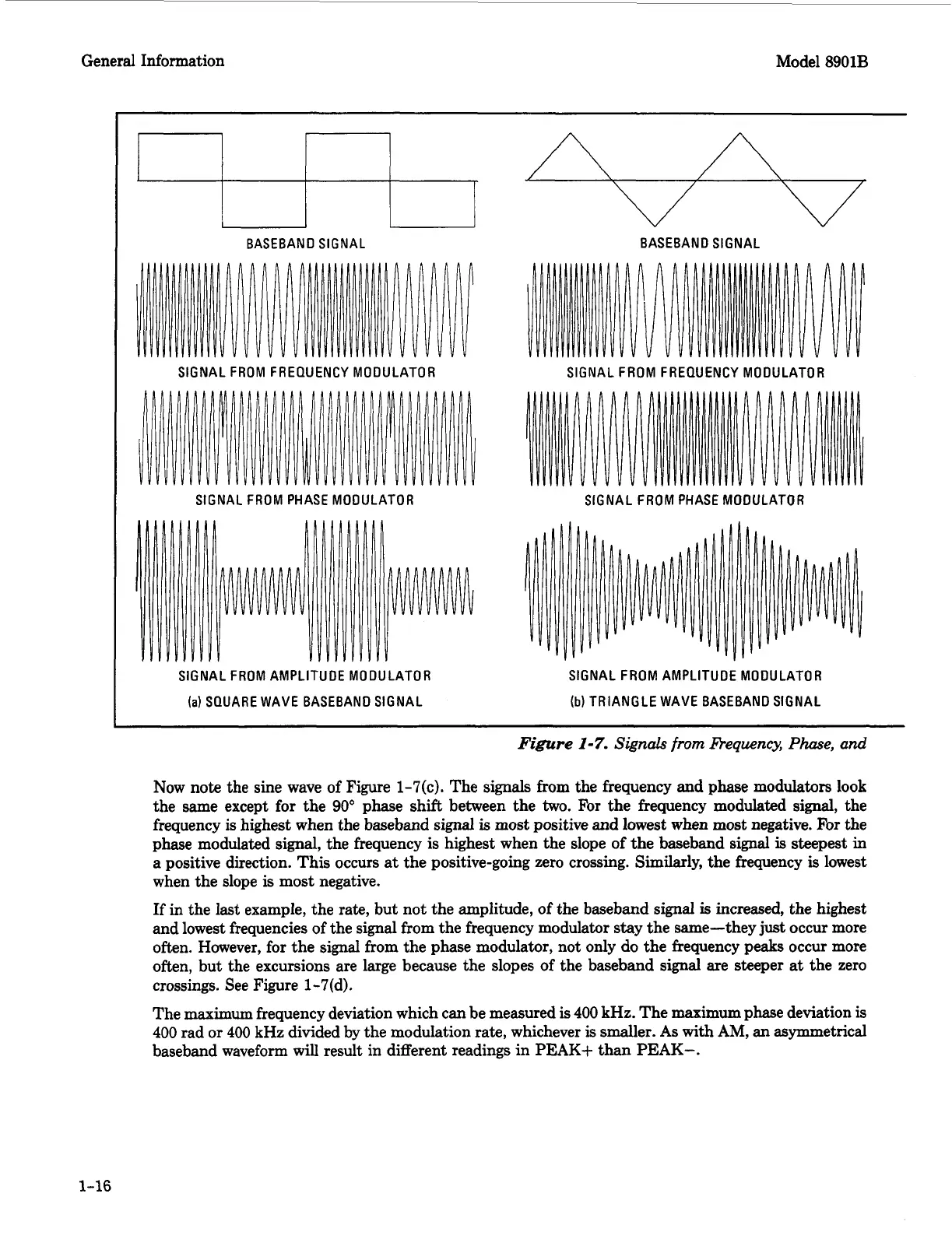
Figure
1-7.
Signals from
Requency,
Phase,
and
Now
note
the sine wave
of
Figure 1-7(c). The signals from the frequency and phase modulators
look
the same except for the
90'
phase shift between the
two.
For
the frequency modulated signal, the
frequency is highest when the baseband signal
is
most positive and lowest when most negative.
For
the
phase modulated signal, the frequency
is
highest when the slope of the baseband signal
is
steepest
in
a positive direction. This occurs
at
the positive-going zero crossing. Similarly, the frequency
is
lowest
when the slope
is
most negative.
If
in the last example, the rate, but not the amplitude,
of
the baseband signal
is
increased, the highest
and lowest frequencies
of
the signal from the frequency modulator stay the same-they just occur more
often. However, for the signal from the phase modulator, not only do the frequency peaks occur more
often, but the excursions are large because the slopes
of
the baseband signal are steeper
at
the zero
crossings. See Figure 1-7(d).
The
maximum
frequency deviation which can be measured
is
400
kHz. The maximum phase deviation is
400
rad
or
400
kHz divided by the modulation rate, whichever is smaller.
As
with
AM,
an asymmetrical
baseband waveform will result in different readings in
PEAK+
than
PEAK-.
1-16