Operation Model 8901B
HP-IB PROGRAM CODES
The HP-IB codes for selecting various combinations of RF
and
IF
filters are provided
in
“PROCE-
DURE”.
BLOCK DIAGRAM
455
kHz
VOLTMETER
AN0 DISPLAY
LOCAL
OSCILLATOR
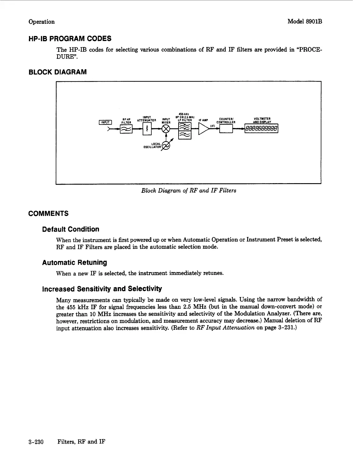
Block
Diagram
of
RF and IF Filters
COMMENTS
Default Condition
When the instrument
is
first powered up or when Automatic Operation
or
Instrument Preset
is
selected,
RF and
IF
Filters are placed in the automatic selection mode.
Automatic Retuning
When a new
IF
is selected, the instrument immediately retunes.
Increased Sensitivity and Selectivity
Many measurements can typically be made on very low-level
signals.
Using the narrow bandwidth of
the
455
kHz
IF
for signal frequencies less than
2.5
MHz (but in the manual down-convert mode) or
greater than
10
MHz increases the sensitivity and selectivity of the Modulation Analyzer. (There are,
however, restrictions on modulation, and measurement accuracy may decrease.) Manual deletion
of
RF
input attenuation also increases sensitivity. (Refer
to
RF Input Attenuation
on page
3-231.)
3-230
Filters, RF and
IF

 Loading...


