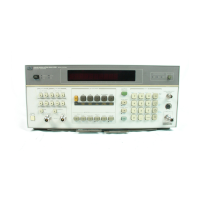
Model
8901B
Operation
23.
External
LO
(Option
030
Only).
Use this special function when making Selective Power
Measurements using an external LO. (Refer
to
Selectiue
Power
Measurements
on
page
3-95
for more
information about this measurement.)
23.0
Return the
LO
to
internal.
23.1
Set the LO
to
external.
23.2
Display the
status
of the
LO
(O=Internal,
l=External).
24.
Selective Power Measurement (Option
030
Only).
Use this special function when measuring
adjacent channel power or single-sideband noise. (Refer
to
Selective Power Measurements on page
3-95
for more information about this measurement.)
24.0
24.1
24.2
24.3
24.4
24.5
24.6
24.7
24.8
24.9
Sets the Modulation Analyzer
to
the Selective Power Measurement Mode.
Selects the wide-bandwidth
IF
filter for adjacent-channel or cellular radio power measure-
ments; displays the
IF
level (in volts).
Establishes the level measured with
24.1
SPCL
as
the
0
dB
reference.
Selects a narrower bandwidth
IF
filter than
24.1
SPCL
for adjacent-channel power
measurements; displays the
IF
level (in volts).
Establishes the level measured with
24.3
SPCL
as
the
0
dB
reference.
Selects
a
very narrow bandwidth
IF
filter
(2.5
kHz)
for the single-sideband noise measure-
ment; displays the
IF
level (in volts).
Establishes the level measured with
24.5
SPCL
as
the
0
dB
reference.
Displays the noise measurement
as
normalized
to
a
1
Hz bandwidth.
Enables setting of the
value
of the noise measurement bandwidth.
Displays the value of the noise measurement bandwidth.
25.
Current Value
of
External Attenuation.
Use
this special function
in
conjunction with
dB
EXT
ATTEN (Blue Key, LOG/LIN)
to
scale level measurements
to
correctly indicate the power
at
the
input of an external attenuator
or
amplifier connected
to
the Modulation Analyzer. (For information
on
setting the
value
of external attenuation, refer
to
Erternal Attenuation
on
page
3-105.)
25.2
Display the current offset in
dB.
(Amplification
is
shown
as
a negative attenuation value.)
27.
Frequency Offset Control.
Use this special function when
making
measurements on down-
converted input signals. (The Modulation Analyzer can measure frequencies
to
42
GHz when an
external mixer and
LO
are
used
to
down-convert the input signal. Refer
to
l+equency offset Control
on page
3-225
for requirements of the local oscillator and mixer.) The Requency Offset Control
special function allows the Modulation Analyzer
to
keep track of the frequencies involved in the
down-conversion.
27.0
Exit the Frequency Offset Mode.
27.1
Enter the Frequency Offset Mode.
27.2
Display the external
LO
frequency.
27.3
Prepare to enter and enable the
LO
frequency. After entering
27.3
SPCL, enter the frequency
of the
LO
(in MHz). Flrequencies
from
0
to
40700
MHz can be entered.
29.0
SINAD Measurement.
Use this special function to make
SINAD
(Signal
to
Noise And
Distortion) measurements on either internally demodulated
signals
or externally applied audio
signals.
real
5SEP88
3-245

 Loading...