Model
8901B
Performance
Tests
Equipment
AMFM Test Source
.............................................................
HP 11715A
Audio Analyzer
...................................................................
HP
8903B
Audio Synthesizer.
................................................................
HP
3336C
HP
89010
MODULATION
ANALYZER
0
OUTPUT
h
UODULATION
OUTPUT/
AUDIO INPUT
oo~oo
(Step
12)
INPUT
-&-
t:::;
000000
O
0000
0
on
0
0000
0
0
0 0
000000
0
0000
0
AUDIO ANALYZER
I
I
I
I
__
0
ooooo(
AUDIO SYNTHESIZER
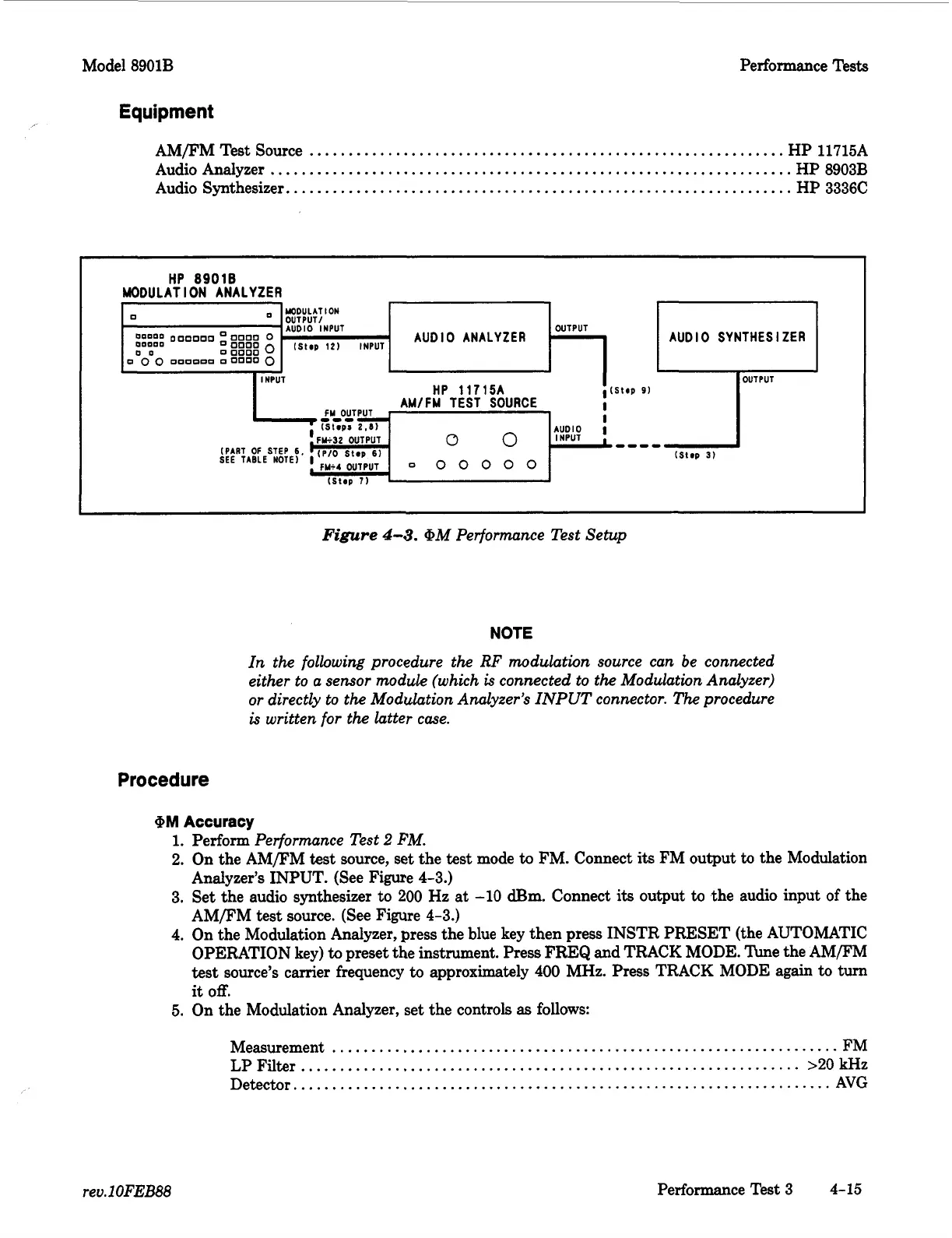
Figure
4-3.
@M Performance Test Setup
NOTE
In the following procedure the
RF
modulation source can be connected
either to a sensor module (which
is
connected to the Modulation Analyzer)
or
directly to the Modulation Analyzer's INPUT connector. The procedure
is
written for the latter case.
Procedure
@M
Accuracy
1.
Perform
Performance Test
2
FM.
2.
On the AMFM
test
source, set the
test
mode
to
FM. Connect its FM output
to
the Modulation
Analyzer's INPUT. (See Figure
4-3.)
3.
Set the audio synthesizer to
200
Hz at
-10
dBm.
Connect
its
output
to
the audio input of the
AMFM test source. (See Figure
4-3.)
4.
On the Modulation Analyzer, press the blue key then press INSTR PRESET (the AUTOMATIC
OPERATION key)
to
preset the instrument. Press FREQ and TRACK MODE. he the AM/FM
test
source's carrier frequency
to
approximately
400
MHz. Press TRACK MODE again
to
turn
it
off.
5.
On the Modulation Analyzer, set the controls
as
follows:
Measurement
.................................................................
FM
LP
Filter
................................................................
>20
kHz
Detector.
....................................................................
AVG
rev.1
OFEB88
Performance Test
3
4-15

 Loading...


