Model
8901B
Performance
Tests
0
WDULATION
OUTPUT/
LOW
AUDIO
INPUT
OUTPUT OUTPUT
AUDIO
ANALYZER
;;:;;
000000
0000
0
niw
00
:
8:::
0
OUTPUT
a
0
0
000000
0
0000
0
Distortion
Accuracy
16.
On the audio analyzer,
set
its
output float switch
to
the float position. Set the audio analyzer’s
oscillator
to
1
kHz
at
1V.
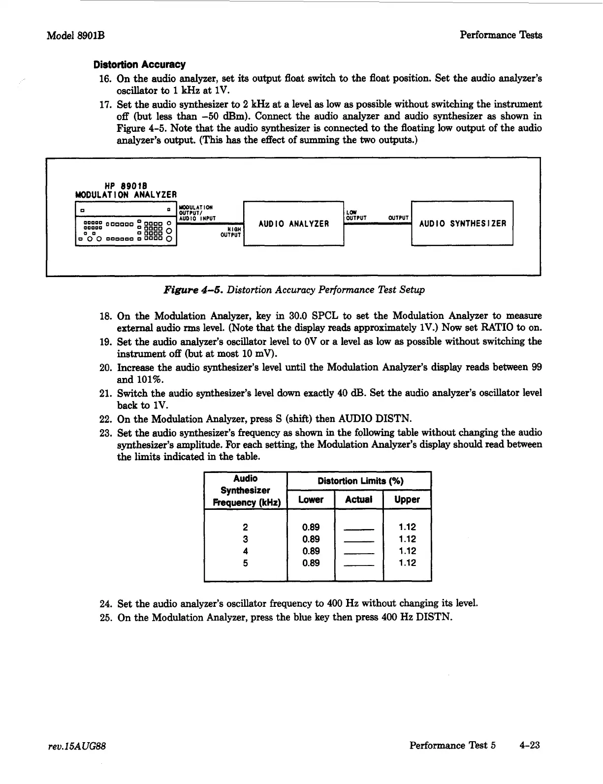
17.
Set the audio synthesizer
to
2
kHz
at
a level
as
low
as
possible without switching the instrument
off (but less than
-50
Bm). Connect the audio analyzer and audio synthesizer
as
shown in
Figure
4-5.
Note
that
the audio synthesizer
is
connected
to
the floating low output of the audio
analyzer’s output.
(This
has
the effect of summing the
two
outputs.)
AUDIO
SYNTHESIZER
HP
89018
MODULATION
ANALYZER
-~
~
Distortion Limits
(%)
Audio
Synthesizer
Frequency
(kHz)
Lower
Actual
Upper
0.89
0.89
0.89
0.89
I
Figure
4-6.
Distortion
Accuracy Performance Test Setup
-
1.12
-
1.12
-
1.12
-
1.12
18.
On the Modulation Analyzer, key in
30.0
SPCL
to
set the Modulation Analyzer
to
measure
external audio
rms
level. (Note
that
the display reads approximately 1V.) Now set RATIO
to
on.
19.
Set the audio analyzer’s oscillator level
to
OV
or
a
level
as
low
as
possible without switching the
instrument
off
(but at most
10
mV).
20. Increase the audio synthesizer’s level
until
the Modulation Analyzer’s display reads between
99
and
101%.
21. Switch the audio synthesizer’s level down exactly
40
dl3.
Set the audio analyzer’s oscillator level
back
to
1V.
22. On the Modulation Analyzer, press
S
(shift) then AUDIO DISTN.
23.
Set the audio synthesizer’s frequency
as
shown in the following table without changing the audio
synthesizer’s amplitude. For each setting, the Modulation Analyzer’s display should read between
the limits indicated
in
the table.
24. Set the audio analyzer’s oscillator frequency
to
400
Hz
without changing
its
level.
25. On the Modulation Analyzer, press the blue key then press
400
Hz
DISTN.
rev.
15AUG88
Performance Test
5
4-23

 Loading...


