Model 8901B Performance Tests
-
POS
VCWP
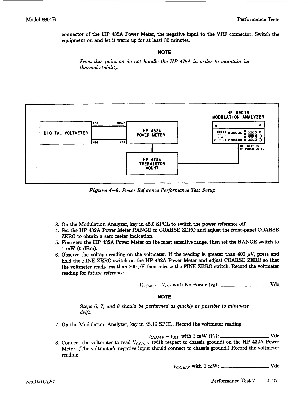
DIGITAL VOLTMETER
NEQ
VRF
connector of the
HP
432A Power Meter, the negative input
to
the
VRF
connector. Switch the
equipment on and let
it
warm up for
at
least
30
minutes.
0
0
000000
0000
0
0
0
0
DODOOP
00000
0
HP
432A
POWER METER
OD
::
888::
0
NOTE
nom this point on do not handle the
HP
478A
in order to maintain its
thermal stability.
Figure
4-6.
Power Reference Performance Test Setup
3. On the Modulation Analyzer, key in 45.0 SPCL
to
switch
the power reference
off.
4. Set the HP 432A Power Meter RANGE
to
COARSE ZERO
and
adjust
the front-panel COARSE
ZERO
to
obtain
a
zero meter indication.
5. Fine zero the
HP
432A Power Meter on the most sensitive range, then
set
the RANGE switch
to
1
mW
(0
dE3m).
6.
Observe the voltage reading on the voltmeter.
If
the reading
is
greater
than
400
pV,
press
and
hold the
FINE
ZERO switch on the HP 432A Power Meter and adjust COARSE ZERO
80
that
the voltmeter reads less than
200
pV
then release the FINE ZERO switch. Record the voltmeter
reading for future reference.
Vco~p
-
VRF
with
No
Power
(Vo):
Vdc
NOTE
Steps
6,
7,
and
8
should
be performed
as
quickly
as
possible to minimize
drift.
7.
On the Modulation Analyzer, key in 45.16 SPCL. Record the voltmeter reading.
Vco~p
-
VRF
with
1
mW
(Vi):
Vdc
8.
Connect the voltmeter
to
read
VCOMP
(with respect
to
chassis ground) on the HP 432A Power
Meter. (The voltmeter’s negative input should connect
to
chassis ground.) Record the voltmeter
reading.
Vco~p
with
1
mW Vdc
rev.lOJUU7
Performance
Test
7
4-27
 Loading...


