Adjustments Model
S901B
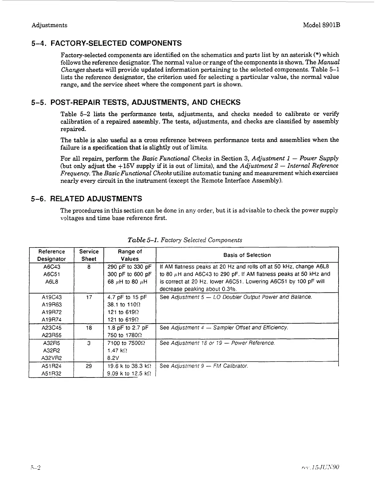
A6C43
A6C51
A6L8
A19C43
A1 9R63
A19R72
A19R74
A23c45
A23R55
5-4.
FACTORY-SELECTED COMPONENTS
Factory-selected components are identified on the schematics and parts list by an asterisk
(*)
which
follows the reference designator. The normal value
or
range of the components is shown. The
Manual
Changes
sheets will provide updated information pertaining
to
the selected components. Table
5-1
lists the reference designator, the criterion used for selecting a particular value, the normal value
range, and the service sheet where the component part is shown.
8
290
pF
to
330
pF
300
pF
to
600
pF
68
IIH
to
80
ILH
4.7
pF
to
15 pF
38.1
to
110!2
121
to
619!2
121
to
619R
1.8
pF
to
2.7
pF
750
to
17800
If
AM
flatness peaks at
20
Hz
and
rolls
off
at
50
kHz,
change
A6L8
to
80
/tH
and
A5C43
to
290
pF.
If
AM
flatness peaks at
50
kHz
and
is
correct
at
20
Hz.
lower
A5C51.
Lowering
A6C51
by
100
pF
will
decrease peaking
about
0.3%.
See Adjustment
5
-
LO
Doubler Output Power
and
Balance.
17
18
See Adjustment
4
-
Sampler Offset
and
Efficiency.
5-5.
POST-REPAIR TESTS, ADJUSTMENTS, AND CHECKS
Table
5-2
lists the performance tests, adjustments, and checks needed
to
calibrate
or
verify
calibration of a repaired assembly. The tests, adjustments, and checks are classified by assembly
repaired.
The table is
also
useful as
a
cross reference between performance tests and assemblies when the
failure is a specification that
is
slightly out of limits.
For
all
repairs, perform the
Basic
Functional Checks
in Section
3,
Adjustment
1
-
Power Supply
(but
only
adjust the
+15V
supply
if
it
is
out of limits), and the
Adjustment
2
-
Internal Reference
Frequency.
The
Basic Functional Checks
utilize automatic tuning and measurement which exercises
nearly every
circuit
in the instrument (except the Remote Interface Assembly).
A32R5
A32R2
A32VR2
A5
1
R2C
A5
1
R32
5-6.
RELATED ADJUSTMENTS
3
7100
to
75000
1.47
k!!
8.2V
19.5
k
to
38.3 k!!
9.09
k
to
12.5
kS1
See Adjustment
76
or
79
-
Power Reference.
29
See
Adjustment
9
-
FP.4
Calibrator.
The procedures in this section can be done in any order, but it is advisable
to
check the power supply
voltages and time base reference first.
Table
5-1.
Factory Selected Components
1
Reference Service Range of
Desia
n
a
tor
1
Sheet
1
Values
Basis
of
Selection

 Loading...


