Adjustments Model 8901B
0
0
VERTICAL
INPUT
:::::
000000
a
0000
0
DO
:;;;;
0
-
0
0
0
000000
a
0000
0
Adjustment
2
INTERNALREFERENCE FREQUENCY
Service
Sheets
22
and
31
Description
An
oscilloscope, triggered by
an
external reference,
is
used
to
monitor the internal reference frequency.
The internal reference frequency
is
adjusted for a stationary waveform on the oscilloscope.
Equipment
F’requency Standard
..........................................................
House
Standard
Oscilloscope
......................................................................
HP
1740A
EXTERNAL
TRIQQER
I
FREQUENCY
OUTPUT
STANDARD
OSCILLOSCOPE
(100
kHt.1
MHt.
5
MHt.OR
10
YHZ)
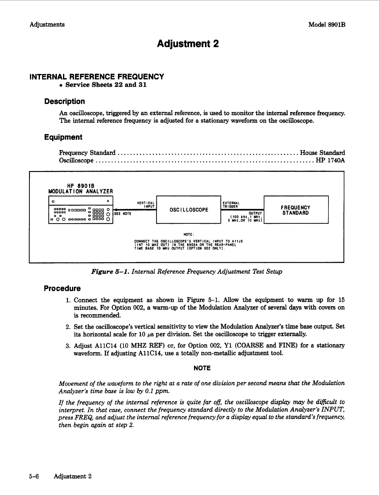
NOTE:
CONNECT THE OSCILLOSCOPE’S VERTICAL INPUT TO
A11J5
(INT
10
YHZ
OUT1 IN THE
8902A
OR
THE REAR-PANEL
TIME
BASE
10
MHt
OUTPUT (OPTION
002
ONLY).
Figure
5-1.
Internal Reference
frequency
Adjustment Test Setup
Procedure
1.
Connect the equipment
as
shown
in
Figure 5-1. Allow the equipment
to
warm up for 15
minutes. For Option
002,
a
warm-up of the Modulation Analyzer of several days with covers on
is
recommended.
2.
Set the oscilloscope’s vertical sensitivity
to
view the Modulation Analyzer’s time base output. Set
its
horizontal scale for 10
ps
per division. Set the oscilloscope
to
trigger externally.
3.
Adjust AllC14 (10 MHZ REF)
or,
for Option
002,
Y1
(COARSE and
FINE)
for a stationary
waveform.
If
adjusting AllC14, use a totally non-metallic adjustment tool.
NOTE
Movement of the waueform to the right at a rate of one division per second means
that
the
Modulation
Analyzer’s
time
base
is
low
by
0.1
ppm.
If the frequency of the internal reference
is
quite far
off,
the oscilloscope display may be difficult to
interpret. In that case, connect the frequency standard directly to the Modulation Analyzer’s
INPUT,
press
FREQ,
and adjust the internal reference frequency for a display equal to
the
standard’s frequency,
then begin again at step
2.
5-6
Adjustment
2
 Loading...


