Model
8901B
Adjustments
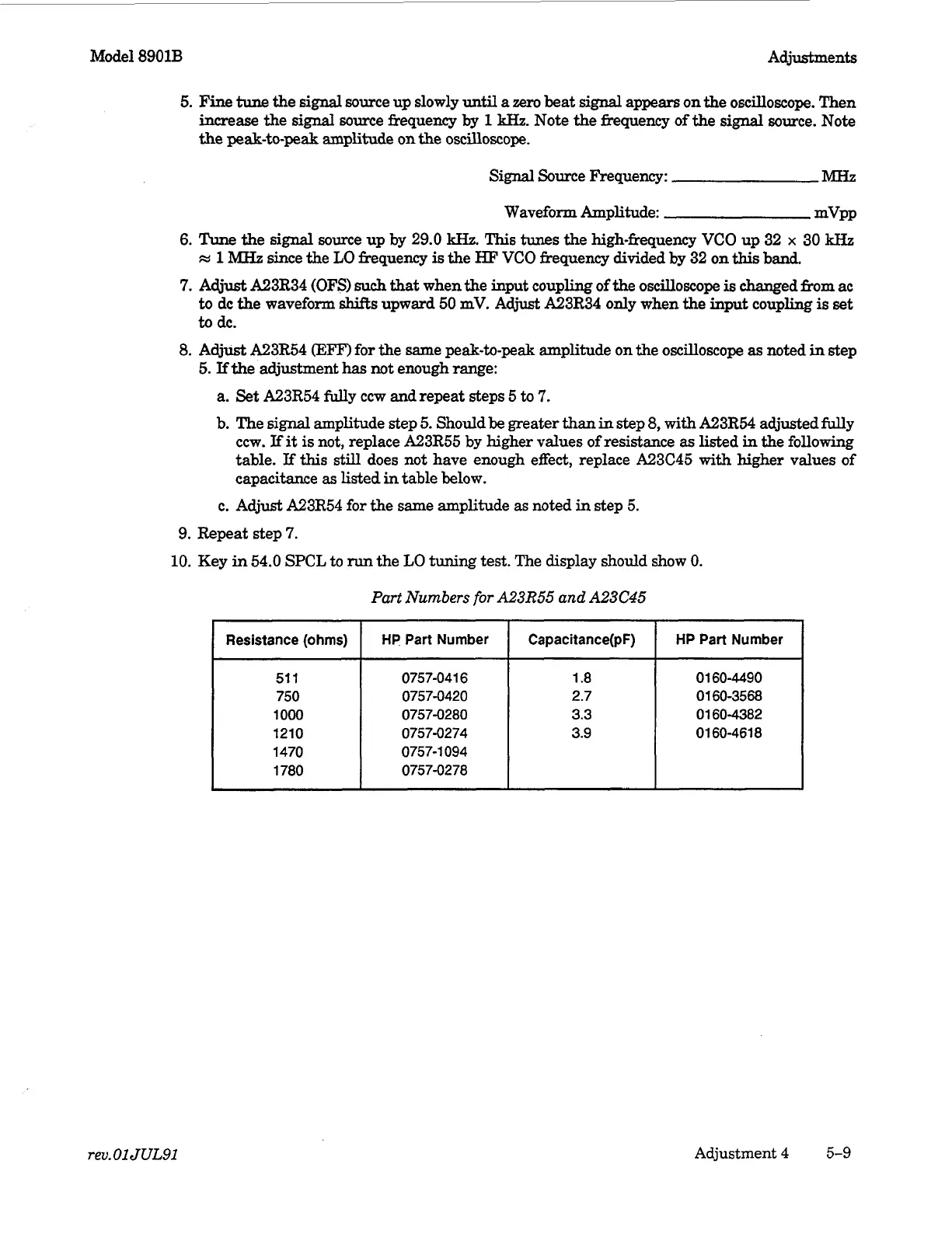
Resistance
(ohms)
5.
Fine
tune
the
signal
some up slowly
until
a
zero
beat
signal
appears
on
the
oscilloscope. Then
increase
the
signal
source frequency
by
1
kHz.
Note
the
fhquency of the
signal
source. Note
the
peak-to-peak amplitude on the oscilloscope.
HP
Part Number Capacitance(pF) HP Part Number
Signal
Source kequency:
MHZ
Waveform Amplitude: mvPP
6.
Tune
the
signal
source up by 29.0
kHz.
This
tunes
the high-frequency VCO up 32
x
30
kHz
M
1
MHz
since the
LO
frequency
is
the
HF
VCO
frequency divided by 32 on
this
band.
7.
Must
A23R34
(OF3
such
that
when
the
input coupling
of
the oscilloscope
is
changed &om
ac
to
dc the waveform
shifts
upward
50
mV. Adjust A23R34 only when the
input
coupling
is
set
to
dc.
8.
Adjust
A23R54
0
for the same peak-to-peak amplitude on the oscilloscope
as
noted
in
step
5.
If
the adjustment
has
not enough range:
a.
Set
A23R54 fully ccw and repeat steps
5
to
7.
b.
The
signal
amplitude step
5.
Should be greater
than
in
step
8,
with A23R54 adjusted fully
ccw.
If
it
is
not, replace
A23R55
by higher values of resistance
as
listed
in
the following
table.
If
this
still does not have enough effect, replace A23C45
with
higher values
of
capacitance
as
listed
in
table below.
c. Adjust A23R54 for the same amplitude as noted
in
step
5.
9.
Repeat step
7.
10.
Key
in
54.0
SPCL
to
run
the
LO
tuning test. The display should show
0.
51
1
750
1000
1210
1470
1780
0757-041
6
0757-0420
0757-0280
0757-0274
0757-0278
0757-1 094
1.8
2.7
3.3
3.9
01
60-4490
01
60-3568
01 60-4382
01 60-461 8
rev.
01 JUL91
Adjustment
4
5-9

 Loading...


