Adjustments Model 8901B
VERTICAL
INPUT
-
A23TPl
‘SAW AWL’
OSCILLOSCOPE
Adjustment
4
0
0
SIGNAL SOURCE
INPUT
:::;:
000000
O
0000
0
,”
BBBB
0
OUTPUT
0
0 0
000000
0
0000
0
SAMPLER EFFICIENCY AND OFFSET
Service
Sheet
18
Description
Using the track-tune mode, the
two
signals into the sampler are configured
so
that
the low-frequency
VCXO
is
at
a
set frequency and the high-frequency VCO tracks the
RF
input signal. The output of the
sampler is observed on an oscilloscope. The
FtF
input
is
tuned
to
locate a zero-beat frequency at the
sampler output then tuned for a
1
MHz beat. The sampler offset and efficiency
(or
frequency response)
are then adjusted
so
that the dc offset
is
50
mV and the amplitude of the
1
MHz waveform
is
the same
as
the zero beat.
NOTE
Improper adjustment
of
efficiency
may
result in the
loop
easily breaking
or
not attaining phase
lock.
Equipment
Oscilloscope
......................................................................
HP 1740A
Signal Source..
......................................................
HP 8640B
or
HP
3336C
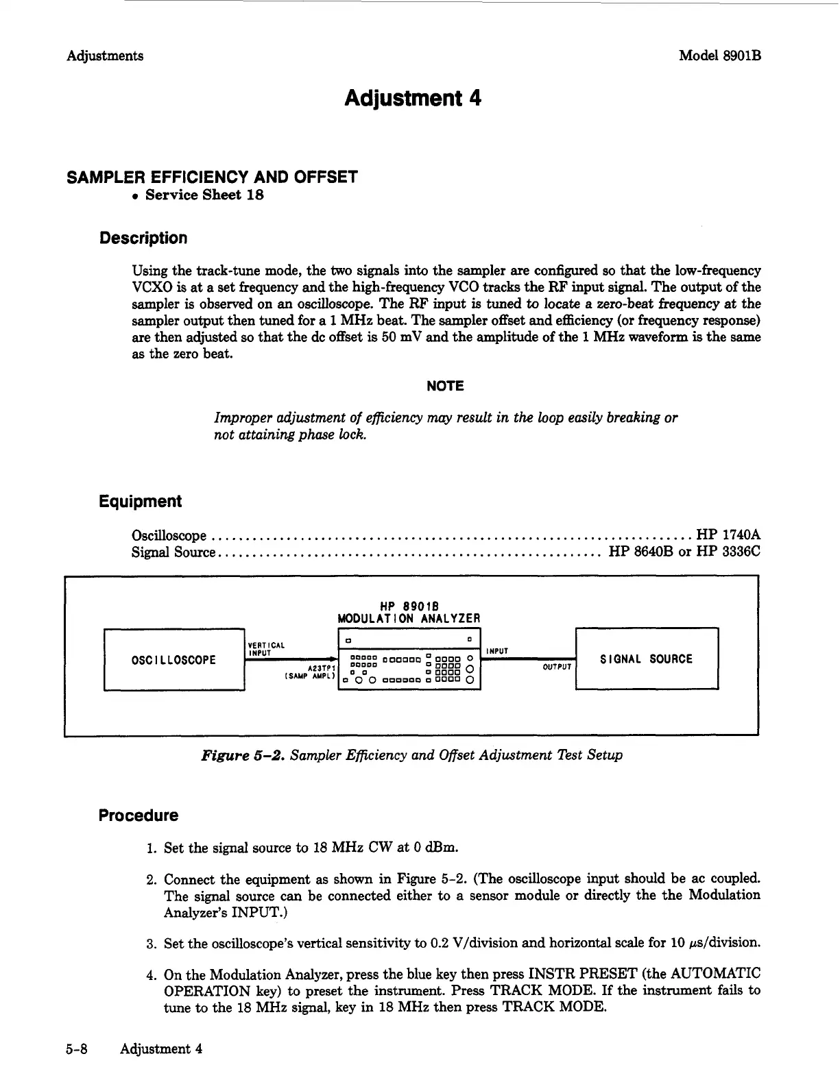
Figure
5-2.
Sampler Efficiency and Offset Adjustment Test Setup
Procedure
1.
Set the signal source
to
18 MHz
CW
at
0
am.
2.
Connect the equipment as shown in Figure
5-2.
(The oscilloscope input should be ac coupled.
The signal source can be connected either to
a
sensor module
or
directly the the Modulation
Analyzer’s INPUT.)
3.
Set the oscilloscope’s vertical sensitivity to
0.2
Vldivision and horizontal scale for
10
ps/division.
4. On the Modulation Analyzer, press the blue key then press INSTR
PRESET
(the AUTOMATIC
OPERATION key) to preset the instrument. Press TRACK MODE.
If
the instrument fails
to
tune to the
18
MHz signal, key in
18
MHz then press TRACK MODE.
5-8
Adjustment 4

 Loading...


