Model
8901B
Adjustments
NOTE
If
the frequency of the power reference
is
already within the proper limits,
do not attempt to adjust the frequency to exactly
50
MHz.
To do
so
may
unnecessarily affect the level.
4.
Reinstall the A32 assembly. (The thumb screw need only be finger tight.)
5.
With the HP 432A Power Meter switched
off
and
the thermistor interconnect cable connected
to
it
but not
to
the thermistor mount, measure the resistance between the center conductor of the
rear-panel VRF' connector and pin
1
(the
first
pin
to
the right
of
the key slot) on the thermistor
end of the interconnect cable. Record the value of the mount resistance for future reference.
(It
should be approximately 2000.)
Mount Resistance
(R):
R
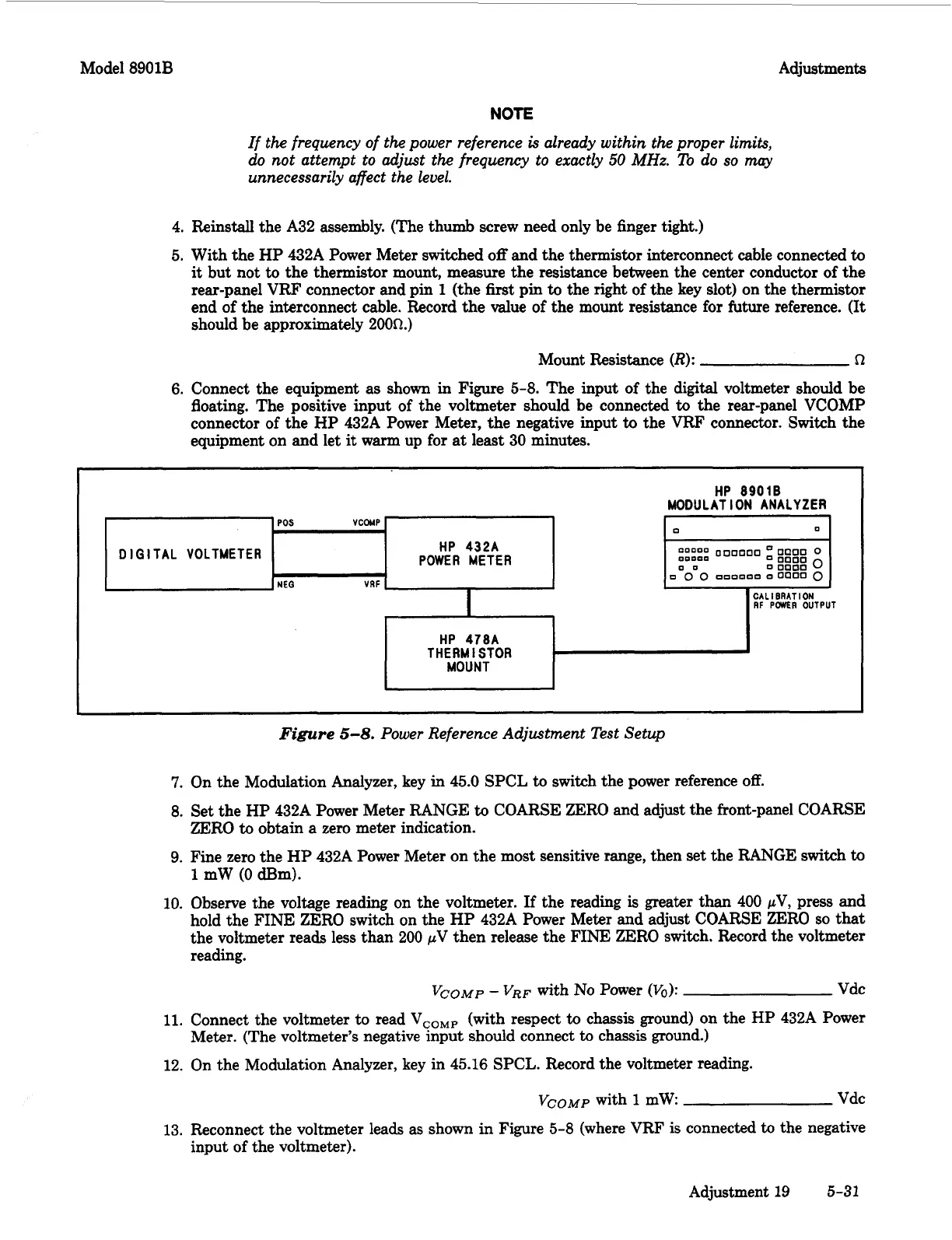
6.
Connect the equipment
as
shown in Figure
5-8.
The input
of
the digital voltmeter should be
floating. The positive input of the voltmeter should be connected
to
the rear-panel VCOMP
connector
of
the HP 432A Power Meter, the negative input
to
the VRF connector. Switch the
equipment on and let
it
warm
up for
at
least 30 minutes.
HP 8901B
MODULATION ANALYZER
POS
VCOMP
0
0
:::::
000000
0000
0
00
0
0000
0
HP
432A
POWER METER
0000
DIGITAL VOLTMETER
0
0
0
nnoooo
00000
0
NEO
VRF
I
CALIBRATION
RF
PWER
OUTPUT
HP
478A
THERMISTOR
MOUNT
Figure
5-8.
Power Reference Adjustment Test Setup
7.
On the Modulation Analyzer, key in
45.0
SPCL
to
switch the power reference
off.
8.
Set the HP 432A Power Meter RANGE
to
COARSE ZERO and adjust the front-panel COARSE
ZERO
to
obtain
a
zero meter indication.
9.
Fine zero the HP 432A Power Meter on the most sensitive range, then set the RANGE switch
to
1
mW
(0
Bm).
10. Observe the voltage reading on the voltmeter.
If
the reading
is
greater than 400
pV,
press and
hold the FINE ZERO switch on the
HP
432A Power Meter and adjust COARSE
ZERO
so
that
the voltmeter reads less than
200
pV
then release the
FINE
ZERO switch. Record the voltmeter
reading.
Vco~p
-
VRF
with
No
Power
(Vo):
Vdc
11.
Connect the voltmeter to read
VCoMp
(with respect
to
chassis ground) on the HP 432A Power
12.
On the Modulation Analyzer, key in
45.16
SPCL. Record the voltmeter reading.
Meter. (The voltmeter's negative input should connect
to
chassis ground.)
Vco~p
with
1
mW Vdc
13. Reconnect the voltmeter leads as shown in Figure
5-8
(where VRF
is
connected
to
the negative
input of the voltmeter).
Adjustment
19
5-31

 Loading...


