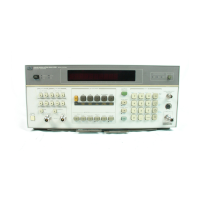
Model 8901B
Installation
Section
2
INSTALLATION
2-1.
INTRODUCTION TO THIS SECTION
This section provides the information needed
to
install the Modulation Analyzer. Included
is
information pertinent to initial inspection, power requirements, line voltage selection, power cables,
interconnection, operating environment, instrument mounting, storage and shipment. This section also
contains
a
procedure for setting the internal HP-IB talk and Iisten address switches and a procedure
for removing the pull-out cards.
2-2.
INITIAL INSPECTION
To
avoid hazardous electrical shock, do not perform electrical tests when
there are signs
of
shipping damage to any portion
of
the outer enclosure
(covers, panels, meters).
Inspect the shipping container for damage.
If
the shipping container
or
cushioning material is
damaged,
it
should be kept until the contents of the shipment have been checked for completeness
and the instrument has been checked mechanically and electrically. Procedures for checking electrical
performance are given in Section
4.
If
the contents are incomplete,
if
there
is
mechanical damage
or defect, or
if
the instrument does not pass the electrical performance test, notify the nearest
Hewlett-Packard office. If the shipping container
is
damaged, or the cushioning material shows
signs
of stress, notify the carrier
as
well as the Hewlett-Packard office. Keep the shipping materials for the
carrier's inspection.
2-3.
PREPARATION
FOR
USE
Power
Requirements
pbmimq
To
avoid the possibility
of
hazardous electrical shock, do not operate this
instrument at line voltages greater than
126.5
Vac with line frequencies
greater than
66
Hz.
Leakage currents at these line settings
may
exceed
3.5
mA.
The Modulation Analyzer requires
a
power source
(+5%
to -10%) of 100, 120,220, or
240
Vac,
48
to
66
Hz single phase. Option
004
also operates from
48
to
440
Hz
single phase, 120 Vac,
(+5%
to
-10%
only). Power consumption
is
200
VA
maximum.
2-
1

 Loading...