Installation Model 8901B
Line Voltage and Fuse Selection
BEFORE PLUGGING THIS INSTRUMENT into the Mains (line) voltage,
be sure the correct voltage and fuse have been selected.
Verify
that
the line voltage selection card and the fuse are matched
to
the power source. Refer
to
Figure 2-1,
Line Voltage and he Selection.
hses may be ordered under HP
part
numbers 2110-0083, 2.5A (250V normal blow) for
115
Vac
operation
and
2110-0043,
1.5A
(250V normal blow) for 230 Vac operation.
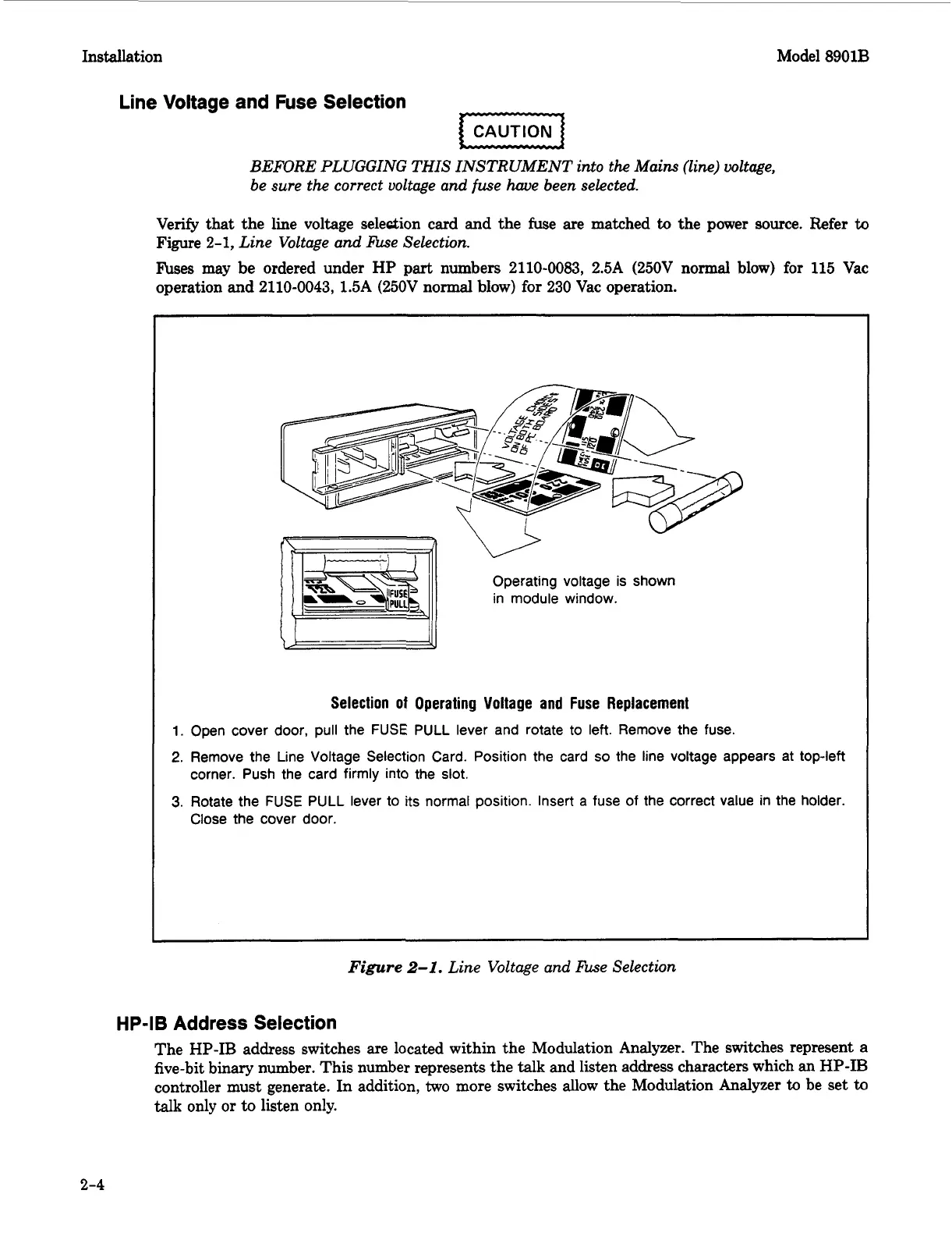
Operating voltage
is
shown
in
module window.
Selection
of
Operating Voltage and
Fuse
Replacement
1.
Open cover door,
pull
the
FUSE
PULL
lever and rotate to left. Remove the fuse.
2.
Remove the Line Voltage Selection Card. Position the card so the line voltage appears at top-left
3.
Rotate the
FUSE
PULL
lever
to
its
normal position. Insert a fuse
of
the correct value
in
the holder.
corner.
Push
the card
firmly
into the slot.
Close the cover door.
Figure
2-1.
Line Voltage and Fuse Selection
HP-IB
Address Selection
The HP-IB address switches
are
located within the Modulation Analyzer. The switches represent
a
five-bit binary number. This number represents the
talk
and listen address characters which
an
HP-IB
controller must generate.
In
addition,
two
more switches allow the Modulation Analyzer
to
be set
to
talk
only or to listen only.
2-4
 Loading...


