Installation Model 8901B
Interconnections
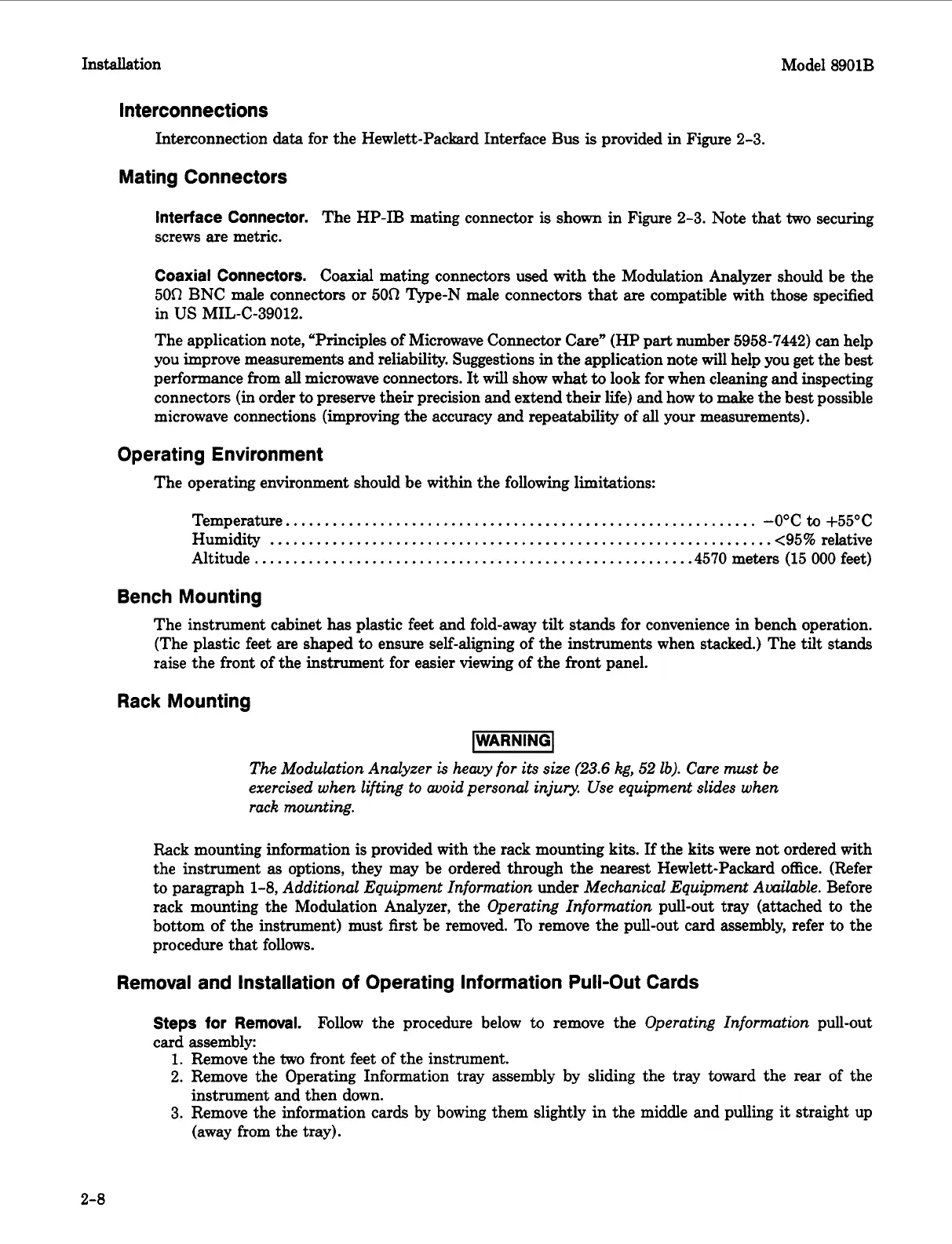
Interconnection data for the Hewlett-Packard Interface Bus
is
provided in Figure 2-3.
Mating Connectors
Interface Connector.
The HP-IB mating connector
is
shown in Figure 2-3. Note that
two
securing
screws are metric.
Coaxial Connectors.
Coaxial mating connectors used with the Modulation Analyzer should be the
50R
BNC male connectors
or
50R
Qpe-N male connectors that are compatible with those specified
The application note, “Principles of Microwave Connector Care” (HP part number 5958-7442) can help
you improve measurements and reliability. Suggestions in the application note will help you get the best
performance from
all
microwave connectors.
It
will
show what
to
look for when cleaning and inspecting
connectors (in order
to
preserve their precision and extend their life) and how
to
make the best possible
microwave connections (improving the accuracy and repeatability of all your measurements).
in
US
MIL-(2-39012.
Operating Environment
The operating environment should be within the following limitations:
Temperature..
..........................................................
-0°C
to
+55”C
Humidity
................................................................
<95%
relative
Altitude
.......................................................
.4570
meters
(15
000
feet)
Bench Mounting
The instrument cabinet
has
plastic feet and fold-away
tilt
stands
for convenience in bench operation.
(The plastic feet are shaped
to
ensure self-aligning of the instruments when stacked.) The tilt
stands
raise the front of the instrument for easier viewing of the front panel.
Rack Mounting
The Modulation Analyzer
is
heavy for its size
(23.6
kg,
52
lb). Care must be
exercised when lifting to avoid personal injuv. Use equipment slides when
rack mounting.
Rack
mounting information is provided with the rack mounting kits.
If
the kits were not ordered with
the instrument
as
options, they may be ordered through the nearest Hewlett-Packard office. (Refer
to paragraph 1-8,
Additional Equipment Information
under
Mechanical Equipment Available.
Before
rack mounting the Modulation Analyzer, the
Operating Information
pull-out tray (attached
to
the
bottom of the instrument) must
first
be removed. To remove the pull-out card assembly, refer
to
the
procedure that follows.
Removal and Installation of Operating Information Pull-Out Cards
Steps for Removal.
Follow the procedure below
to
remove the
Operating Information
pull-out
card assembly:
1.
Remove the
two
front feet of the instrument.
2. Remove the Operating Information tray assembly by sliding the tray toward the rear of the
3.
Remove the information cards by bowing them slightly in the middle and pulling
it
straight up
instrument and then down.
(away from the tray).
2-8
 Loading...


