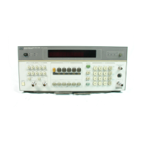
Operation Model 8901B
Before the Modulation Analyzer
is
switched on, all protective earth termi-
nals, extension cords, auto-transformers, and devices connected to
it
shouM
be connected to a protective earth socket. Any interruption of the protective
earth grounding will cause a potential shock hazard that could result in
personal
injury.
For
continued protection against fire hazard, replace the line fuse with a
250V normal blow fuse of the same rating. Do not use repaired fuses
or
short-circuited fuseholders.
The Modulation Analyzer
has
a
standby state and
an
on
state.
Whenever the power cable
is
plugged in,
an
internal power supply
is
activated. In instruments supplied with the high-stability reference (Option
002) the supply energizes the internal reference oven.
If
the Modulation Analyzer
is
already plugged
in, set the
POWER
switch to
ON.
If
the power cable is not plugged 'in, follow these instructions:
1.
Check
that
the line voltage setting matches the power source. (See Figure
2-1,
Line Voltage and
he Selection.)
2.
Check that the fuse rating
is
appropriate for the line voltage used. (See Figure 2-1,
Line Voltage
and fie Selection.)
fise ratings are provided in the paragraph
Operator's Maintenance
in
this section.
3.
Plug in the power cable.
4.
Set the
POWER
switch
to
ON.
NOTE
When the POWER switch
is
set to
ON,
all front-panel indicators
light
for approximately
10
seconds after which the instrument
is
ready to be
operated.
3-5.
INSTRUMENT FEATURES
Front-panel controls, indicators, and connectors are illustrated and referenced
to
text in Figure
3-1.
The text for this figure describes the various functions of the Modulation Analyzer.
At
the end of each
description is
a
reference
to
a
detailed operating instruction
that
contains more details on this topic.
Rear-panel features are shown and referenced to text in Figure
3-2.
The text for this figure provides
a quick reference for rear-panel signal levels and frequencies and also includes the impedances at the
rear-panel connections.
The information in parenthesis
at
the end of each feature summary provides the title of the
Detailed
Operating Instructions
relevant
to
the feature.
3-4

 Loading...