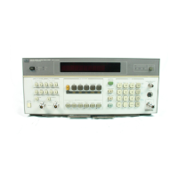
Operation Model 8901B
Front-Panel Features
The following list provides a brief description of each feature. The information
in
brackets provides
the title of the
Detailed Operating Instructions
relevant to the feature. The index lists page numbers
for the instructions.
1.
MEASUREMENT keys enable the Modulation Analyzer
to
make and display the selected
measurement. [See
AM, FM,
@M,
RF Power, RF Input FYequency, Audio FYequency, Audio
Distortion, IF Level, Tuned RF Level, RF FYequency Error.]
2.
Numeric Display shows measurement results, error codes,
or
instrument
or
Special Function
status.
3.
Display Annunciators indicate the measurement result units. They also indicate that some
measurement functions are enabled. All these annunciators are displayed when the Modulation
Analyzer
is
first turned on.
4.
AUTOMATIC OPERATION enables the Modulation Analyzer
to
automatically tune and
to
autorange to make the selected measurement. [See
Automatic Operation.]
5.
INSTR PRESET (Blue Key) configures the Modulation Analyzer to
its
power-up condition. [See
Instrument Preset.]
6.
TRACK
MODE
and
AUTO
TUNING (Blue Key) select the tuning mode of the Modulation
Analyzer. [See
RF
FYequency Tuning.]
7.
STORE (Blue Key) and RECALL (Blue Key) enable the Modulation Analyzer
to
store and recall
up to eight measurement states. [See
Store/Recall.]
8.
WATTS, pV, mV, and VOLTS keys (all used with the Blue Key) enable selection of different
units
for
level measurements.
9.
MHz completes the keyboard entry
of
frequencies for various functions. This key
is
also used
to
complete the entry of frequencies used with RF Power calibration factors. [See
RF FYequency
nning, FYequency Offset Mode,
RF
Power.]
10. MODULATION OUTPUT/AUDIO INPUT connector provides either an output for the mod-
ulation recovered from the RF INPUT connector
or
an input for external audio signals
to
be
processed by the audio circuitry. The MODULATION OUTPUT annunciators indicate the type
of
recovered modulation available as the output. The AUDIO INPUT key selects whether the
internally demodulated signal
or
an external audio signal
is
to be processed by the Modulation
Analyzer’s audio circuitry. [See
Modulation OutputlAudio Input, Audio FYequency, Audio
Distortion
and
Level, SINAD.]
11.
7%
CAL FACTOR (Blue Key) causes the Modulation Analyzer to display the current calibration
factor for the selected measurement. This key is also used to complete the entry of calibration
factors for various functions. [See
AM Calibration, FM Calibration, RF Power.]
it tuned to last. [See
FFequency Offset Mode, RF Power Calibration Factors.]
12.
DISPLAY FREQ (Blue Key) causes the Modulation Analyzer to display the RF frequency that
’
13. SENSOR connector provides the input for the power sensor. [See
RF Power.]
14.
kHz
0
and kHz
4
complete keyboard entry of frequency step-size (in kHz) for step tuning,
or
change the frequency in the increments specified. [See
RF FYequency Tuning.]
15.
DISPLAY FREQ INCR (Blue Key) causes the Modulation Analyzer to display the increment
step-size. [See
RF Frequency Tuning.]
16. INPUT couples the RF input signal into the instrument. [See
RF Input Requency.]
17. SPCL completes entry
of
Special Function codes that access additional instrument operations.
Without a preceeding numeric entry, the SPCL key causes a display
of
the status
of
Special
Functions
1
through
10.
[See
Special finctions.]
3-6

 Loading...