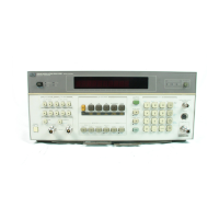
Model
8901B
Operation
18.
(-)
(Blue Key) enables input
data
to
be entered
as
a negative value.
19.
RANGE HOLD freezes the current ranges being used
by
the Modulation Analyzer. [See
Range Hold.]
20.
Blue Key is a shift key that enables some keys
to
have
two
different functions. Any function
printed in blue can be selected when the key associated with
it
is
pressed after the Blue Key.
(The Blue Key flashes
at
the current measurement rate whenever it
is
pressed.)
21.
DISABLE ERROR (Blue Key) disables Error
01
through Error
04.
[See
Error Message
22.
23.
24.
25.
26.
27.
28.
29.
30.
31.
32.
33.
34.
35.
36.
37.
38.
Disable Control.]
LOG/LIN causes measurements to alternate between logarithmic and linear units. [See
Ratio and
LoglLin.
]
dB
EXT ATTEN (Blue Key) enables level measurements
to
be offset with external attenuation
or gain. [See
External Attenuation.]
RATIO and PREVIOUS
RATIO
(Blue Key) cause the current measurement
to
be compared
to
a
reference. [See
Ratio and LoglLin.1
Operating Information
pull-out cards are quick operating references that list Special Function,
HP-IB, and Error codes, show a simplified block diagram for the Modulation Analyzer, and
provide basic information for
RF
Power
and
AMFM Calibration.
DETECTOR keys select the audio detector used
to
measure the modulation.
[See
Audio Detectors,
Audio Distortion and Level, SINAD.]
1
kHz DISTN (Blue Key) and
400
Hz DISTN (Blue Key) enable the Modulation Analyzer
to
make audio measurements on either
1
kHz
or
400
Hz audio
signals.
[See
Audio Distortion and
Level, SINAD.]
CALIBRATION AMFM OUTPUT makes available a precisely modulated signal used
to
improve
the Modulation Analyzer’s AM or FM accuracy. [See
AM Calibration, FM Calibration.]
CALIBRATE and SAVE CAL (Blue Key) enable the Modulation Analyzer
to
calibrate and save
the resulting calibration factor for either
RF
Power, AM, or FM. The CALIBRATE key
also
initiates tuned RF level calibration operations. [See
AM Calibration, FM Calibration, RF Power.]
CALIBRATION RF POWER OUTPUT makes available a
50
MHz,
1
mW power reference
used
to
precisely determine the sensitivity of the external power sensor. [See
RF Power.]
SET
REF (Blue Key) is not a Modulation Analyzer function.
POWER switch applies power
to
the Modulation Analyzer when set
to
ON. [See
Instrument
Preset.
]
ZERO causes the Modulation Analyzer
to
cancel any dc offset that may be present in the power
sensor. [See
RF Power.]
PRE DISPLAY enables FM deviation
to
be measured before
or
after de-emphasis. [See
FM
De-Emphasis.]
FM DE-EMPHASIS networks equalize pre-emphasized FM. [See
FM De-Emphasis.]
HP (High-Pass) and LP (Low-Pass) FILTERS limit the demodulated signal bandwidth. [See
Audio Filters.]
LOCAL returns the Modulation Analyzer to keyboard control from remote (HP-IB) control.
HP-IB Annunciators indicate remote operation status.
3-7

 Loading...