EasyManuals Logo
Home>HP>Switch>A5800 Series

HP A5800 Series Installation Guide

HP A5800 Series
146 pages
To Next Page IconTo Next Page
To Previous Page IconTo Previous Page
Page #119 background imageLoading...
Page #119 background image
113
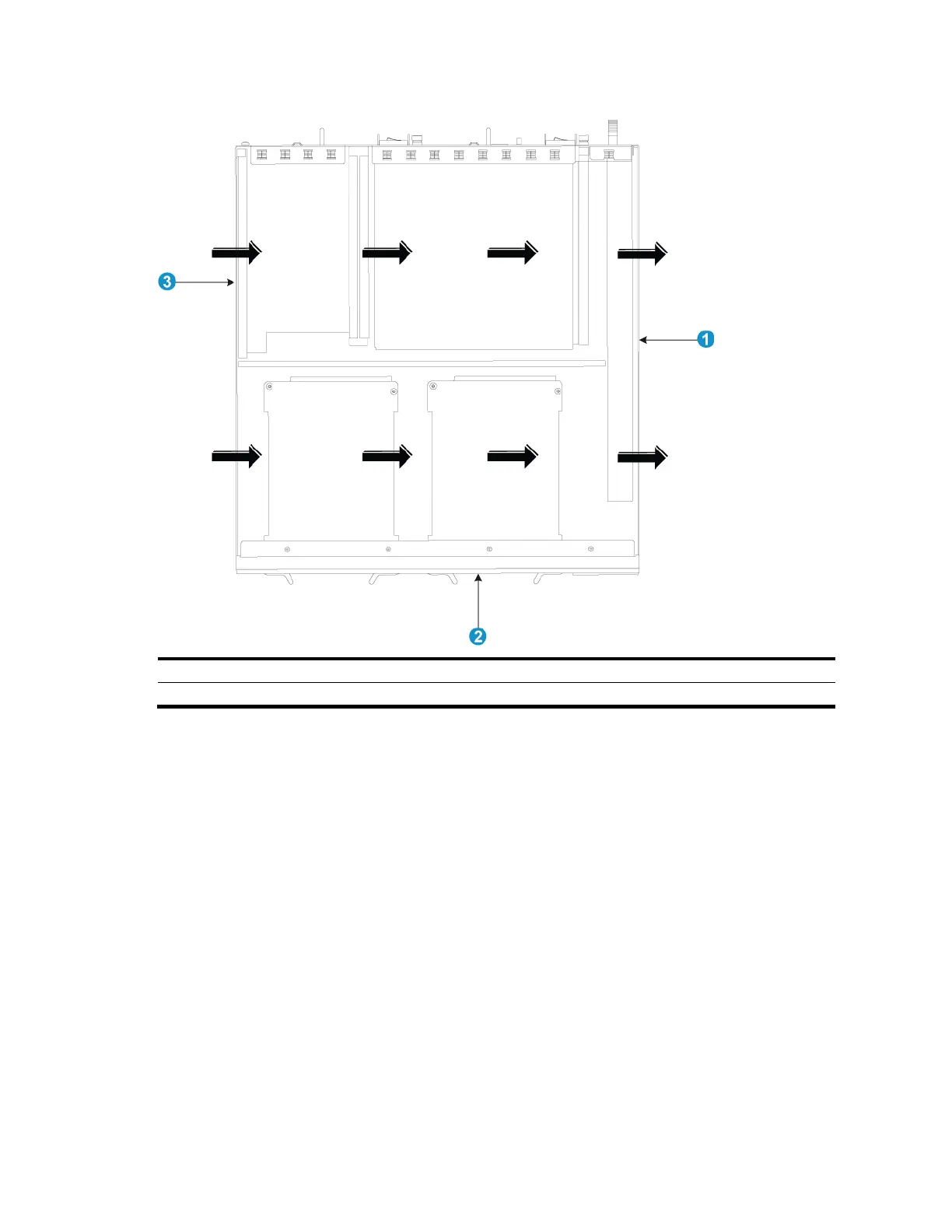
Figure 95 Airflow through the upper half of the chassis
(1) Outlet air vents in the fan tray panel
(2) Front panel
(3) Side inlet air vents
A5800-48G (1 slot)/A5800-48G TAA (1 slot)
Figure 96 shows the airflow design for the A5800-48G (1 slot) and A5800-48G TAA (1 slot) switches.
Cool air flows in from the left side of the chassis, circulates through the chassis and the interface card,
and exhausts out the right side of the chassis.

Table of Contents

Other manuals for HP A5800 Series

Questions and Answers:

Question and Answer IconNeed help?

Do you have a question about the HP A5800 Series and is the answer not in the manual?

HP A5800 Series Specifications

General IconGeneral
BrandHP
ModelA5800 Series
CategorySwitch
LanguageEnglish

Related product manuals