30
Figure 38 Connecting the switch to a –54 VDC output RPS
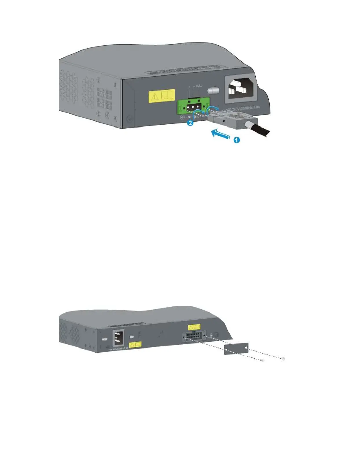
Connecting the switch to a 12 VDC output RPS
This section applies to the A5800-48G (1 slot), A5800-48G TAA (1 slot), A5800-24G, and A5800-24G
TAA switches.
To connect these switches to the RPS that provides 12 VDC output:
1. Loosen the captive screws on the RPS receptacle and remove the cover, as shown in Figure 39.
Put away the cover and re-install it after you remove the RPS DC-input power connector.
2. Unpack the RPS power cord, identify the plug for connecting to the switch, correctly orient the plug
with the RPS receptacle on the switch chassis, and insert the plug into the receptacle (see callout 1
in Figure 40).
3. The power receptacle is foolproof. If you cannot insert the plug into the receptacle, re-orient the
plug rather than use excessive force to push it in.
4. Tighten the screws on the plug with a flat-blade screwdriver to secure the plug in the power
receptacle (see callout 2 in Figure 40).
5. Connect the other end of the power cord to the RPS.
Figure 39 Removing the cover over the RPS receptacle
 Loading...


