85
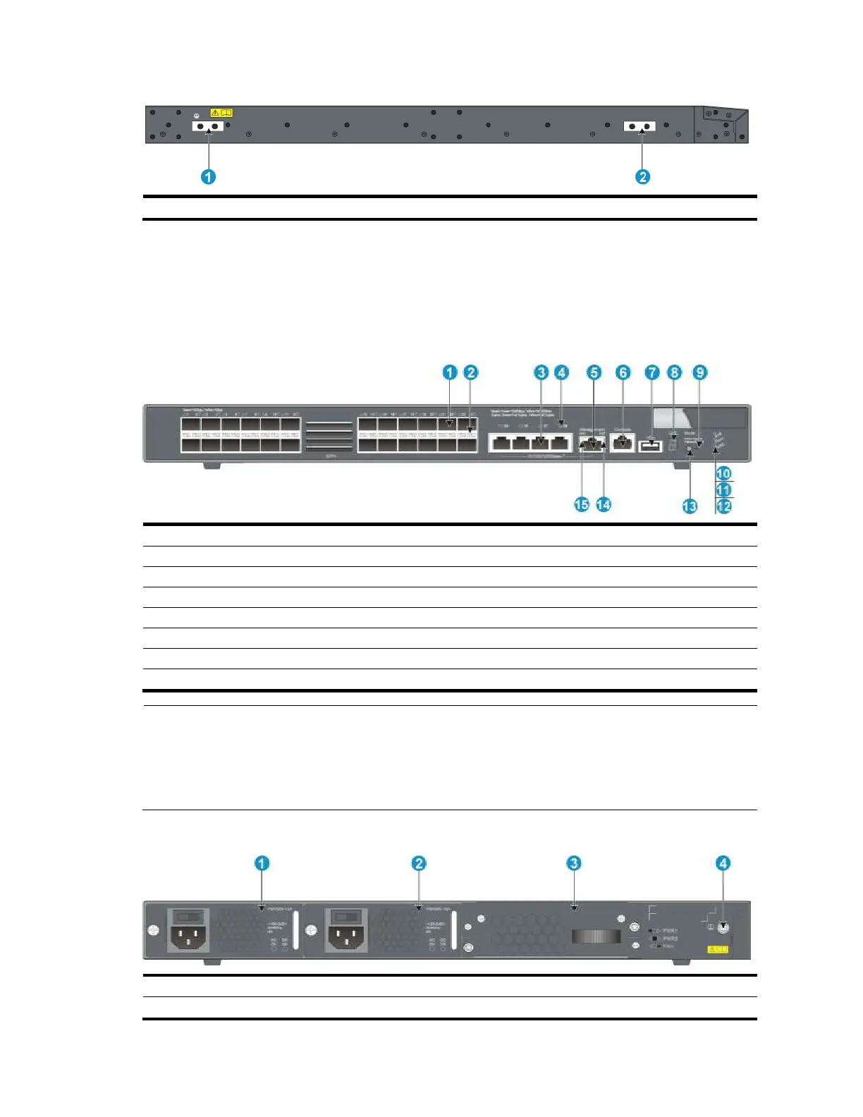
Figure 88 Left side panel
(1) Primary grounding point
(2) Auxiliary grounding point 1
A5820X-24XG-SFP+/A5820X-24XG-SFP+ TAA
panel views
Figure 89 Front panel
(3) 10/100/1000Base-T auto-sensing Ethernet port
(4) 10/100/1000Base-T Ethernet port LED
(5) Management Ethernet port
(10) System status LED (SYS)
(11) Power supply 1 status LED (PWR1)
(12) Power supply 2 status LED (PWR2)
(13) Port LED mode switching button
(14) ACT LED for the management Ethernet port
(15) LINK LED for the management Ethernet port
NOTE:
The SFP+ ports are numbered from left to right and from top to bottom, with you facing the front panel. The first
top left SFP+ port is numbered 1, the first bottom left SFP+ port is numbered 2, the second top left port is
numbered 3, and so on.
The 10/100/1000Base-T auto-sensing Ethernet ports, from left to right, are numbered 25, 26, 27, and 28.
Figure 90 Rear panel
(3) Hot swappable fan tray
 Loading...


