122
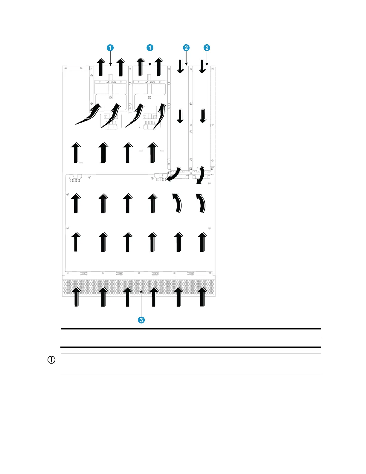
Figure 104 Airflow through the chassis (with LSWM1FANSCB fan trays)
(2) Power supply air vents
(3) Network port-side air vents
IMPORTANT:
The chassis and the power supplies use separate air aisles. Make sure that both aisles are not blocked.
A5820X-24XG-SFP+/A5820X-24XG-SFP+ TAA
Figure 105 shows the airflow through the A5820X-24XG-SFP+/A5820X-24XG-SFP+ TAA chassis and
power supplies. Cool air flows in from the two sides and front of the chassis, circulates through the
chassis and power supplies, and exhausts through the air vents in the fan tray panel and the power
supply panels.
 Loading...


