EasyManuals Logo
Home>HP>Switch>A5800 Series

HP A5800 Series Installation Guide

HP A5800 Series
146 pages
To Next Page IconTo Next Page
To Previous Page IconTo Previous Page
Page #93 background imageLoading...
Page #93 background image
87
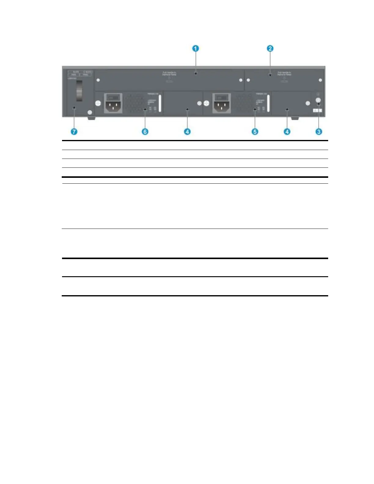
Figure 92 Rear panel
(1) OAP card slot
(2) Filler panel (do not remove it)
(3) Grounding screw
(4) Filler module (do not remove it)
(5) Power supply slot 2
(6) Power supply slot 1
(7) Hot swappable fan tray
NOTE:
The A5820X-14XG-SFP+ (2 slots) and A5820X-14XG-SFP+ TAA (2 slots) switches come with power supply slot 1
empty and power supply slot 2 covered by a filler panel. You can install one or two power supplies for your
switch as needed. In this figure, two PSR300-12A AC power supplies are installed in the slots.
These two switches also come with the OAP card slot covered by a filler panel.
Environmental specifications
Chassis
Operating
temperature
Relative humidity
Fire resistance compliance
All chassis
0°C to 45°C (32°F to
113°F)
10% to 90%, noncondensing
UL60950-1, EN60950-1,
IEC60950-1, GB4943

Table of Contents

Other manuals for HP A5800 Series

Questions and Answers:

Question and Answer IconNeed help?

Do you have a question about the HP A5800 Series and is the answer not in the manual?

HP A5800 Series Specifications

General IconGeneral
BrandHP
ModelA5800 Series
CategorySwitch
LanguageEnglish

Related product manuals