87
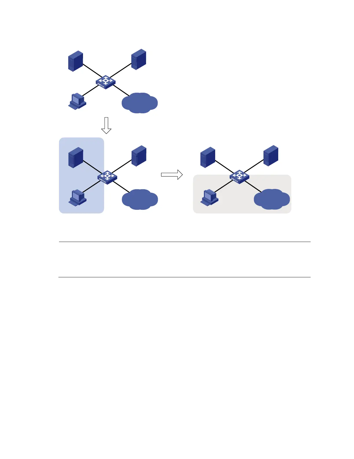
Figure 34 Network diagram for 802.1X with guest VLAN and VLAN assignment configuration
Internet
Update server Authentication server
Host
VLAN 10
GE1/0/1
VLAN 10
GE1/0/2
VLAN 5
GE1/0/3
VLAN 2
GE1/0/4
Device
Internet
Update server Authentication server
Host
VLAN 10
GE1/0/1
VLAN 1
GE1/0/2
VLAN 5
GE1/0/3
VLAN 2
GE1/0/4
Device
Internet
Update server Authentication server
Host
VLAN 10
GE1/0/1
VLAN 5
GE1/0/2
VLAN 5
GE1/0/3
VLAN 2
GE1/0/4
Device
Port added to the
guest VLAN
User gets
online
Configuration procedure
NOTE:
The following configuration procedure covers most AAA/RADIUS configuration commands on the
device. The configuration on the 802.1X client and RADIUS server are not shown. For more
information about AAA/RADIUS configuration commands, see
Security Command Reference
.
1. Make sure that the 802.1X client can update its IP address after the access port is assigned to the
guest VLAN or a server-assigned VLAN. (Details not shown)
2. Configure the RADIUS server to provide authentication, authorization, and accounting services.
Configure user accounts and server-assigned VLAN, VLAN 5 in this example. (Details not shown)
3. Create VLANs, and assign ports to the VLANs.
<Device> system-view
[Device] vlan 1
[Device-vlan1] port gigabitethernet 1/0/2
[Device-vlan1] quit
[Device] vlan 10
[Device-vlan10] port gigabitethernet 1/0/1
[Device-vlan10] quit
[Device] vlan 2
[Device-vlan2] port gigabitethernet 1/0/4
[Device-vlan2] quit
[Device] vlan 5
[Device-vlan5] port gigabitethernet 1/0/3

 Loading...


