(4) 1000 Mbps optical Ethernet interface LED (SFP1)
(5) Run LED (RUN)
Table 1-18 Description of FIP-100 LEDs
LED Status Meaning
RUN (green)
Off No power input is available or the FIP-100 has failed.
Slow blinking (1 Hz) The FIP-100 is working normally.
Fast blinking (8 Hz)
Application program is being loaded (in this case, never power
off the device or hot-swap the FIP-100; otherwise, the FIP-100
may be damaged) or the FIP-100 is not working.
SFP0 and SFP1
(yellow/green)
Off No optical link is present.
Solid green An optical link is present.
Blinking green Data is being sent or received at a rate of 1000 Mbps.
Solid yellow The optical transceiver has failed in POST.
GE0 and GE1
(yellow/green)
Off No link is present.
Solid green A 1000 Mbps link is present.
Blinking green Data is being received or transmitted at a rate of 1000 Mbps.
Solid yellow A 10/100 Mbps link is present.
Blinking yellow Data is being received or transmitted at a rate of 10/100 Mbps.
Slots
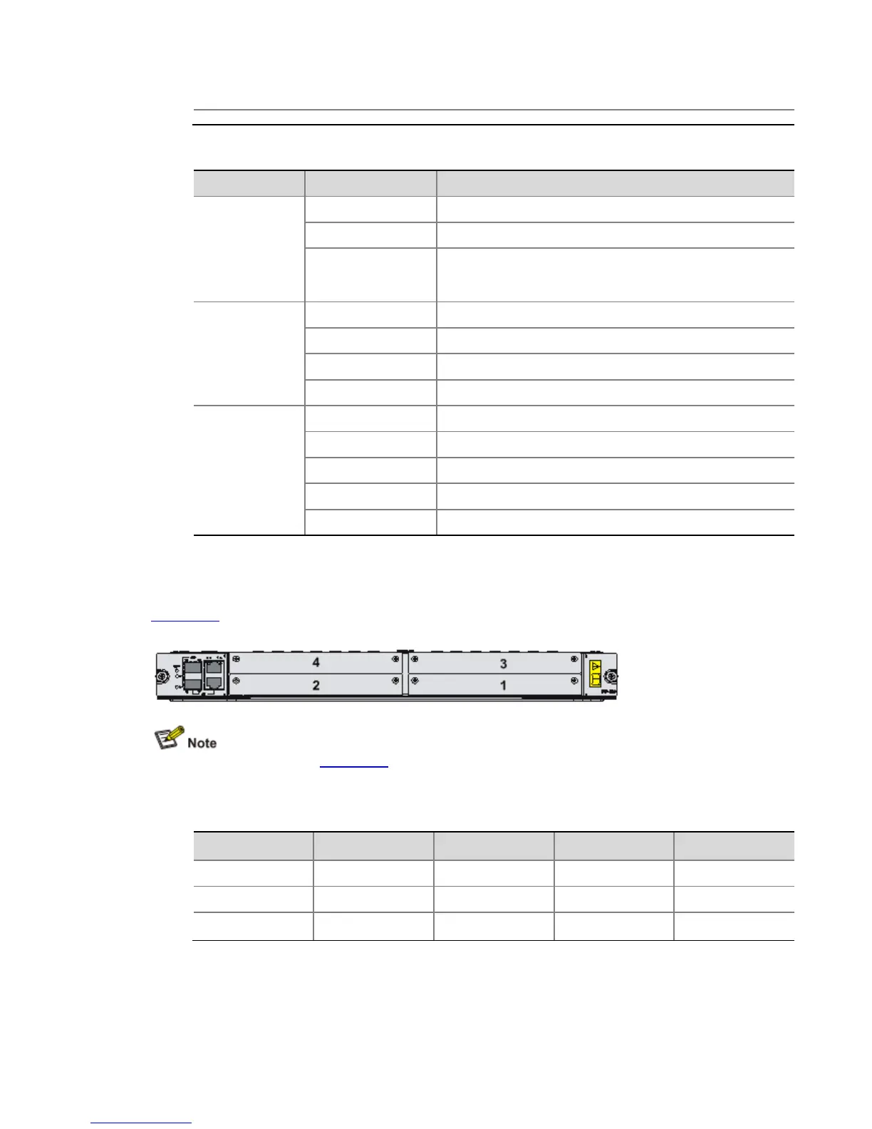
FIP-100s can be inserted into Slot 0 through Slot 3, and Slot 6 through Slot 9 on the A6616. The
slots on a FIP-100 are numbered 1 to 4 from the bottom up and from right to left, as shown in
Figure 1-16.
Figure 1-16 Interface module slots on the FIP-100
The numbers 1 through 4 in Figure 1-16 represent Slot 1 through Slot 4 respectively.
Maximum interface modules provided by FIP-100s in full configuration
Table 1-19 Maximum interface modules provided by FIP-100s in full configuration
Interface module One RPE-X1 Two RPE-X1s One RSE-X1 Two RSE-X1s
FIP-100 8 8 Not supported Not supported
MIMs 32 32 — —
HIMs Not supported Not supported Not supported Not supported