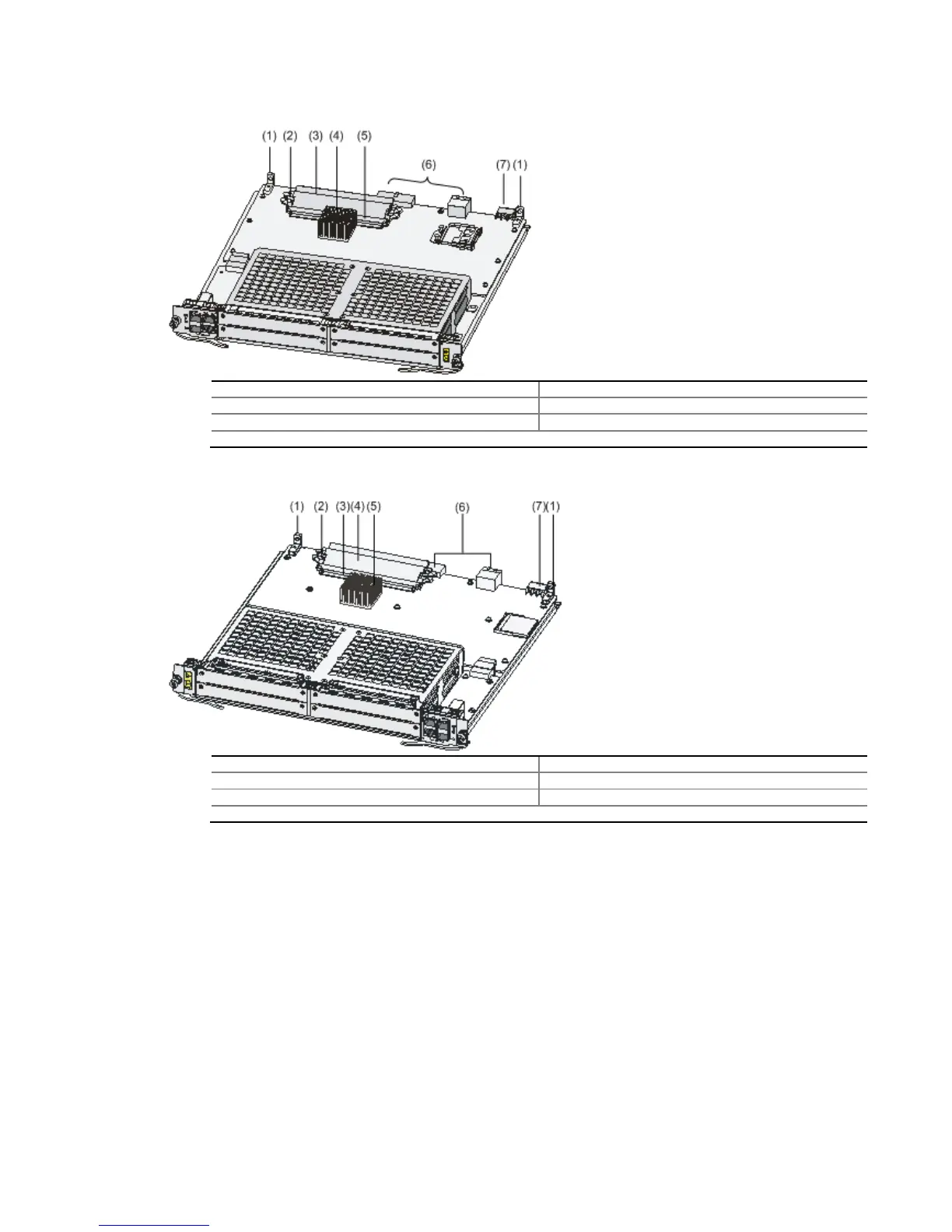
Figure 4-20 Interior structure of the FIP-100
(1) Positioning holes (2) Release latch
(3) Memory module (4) CPU heatsink
(5) Memory module slot (6) Bus connectors
(7) Power connector
Figure 4-21 Interior structure of the FIP-110
(1) Positioning holes (2) Release latch
(3) Memory module slot (4) Memory module
(5) CPU heatsink (6) Bus connectors
(7) Power connector