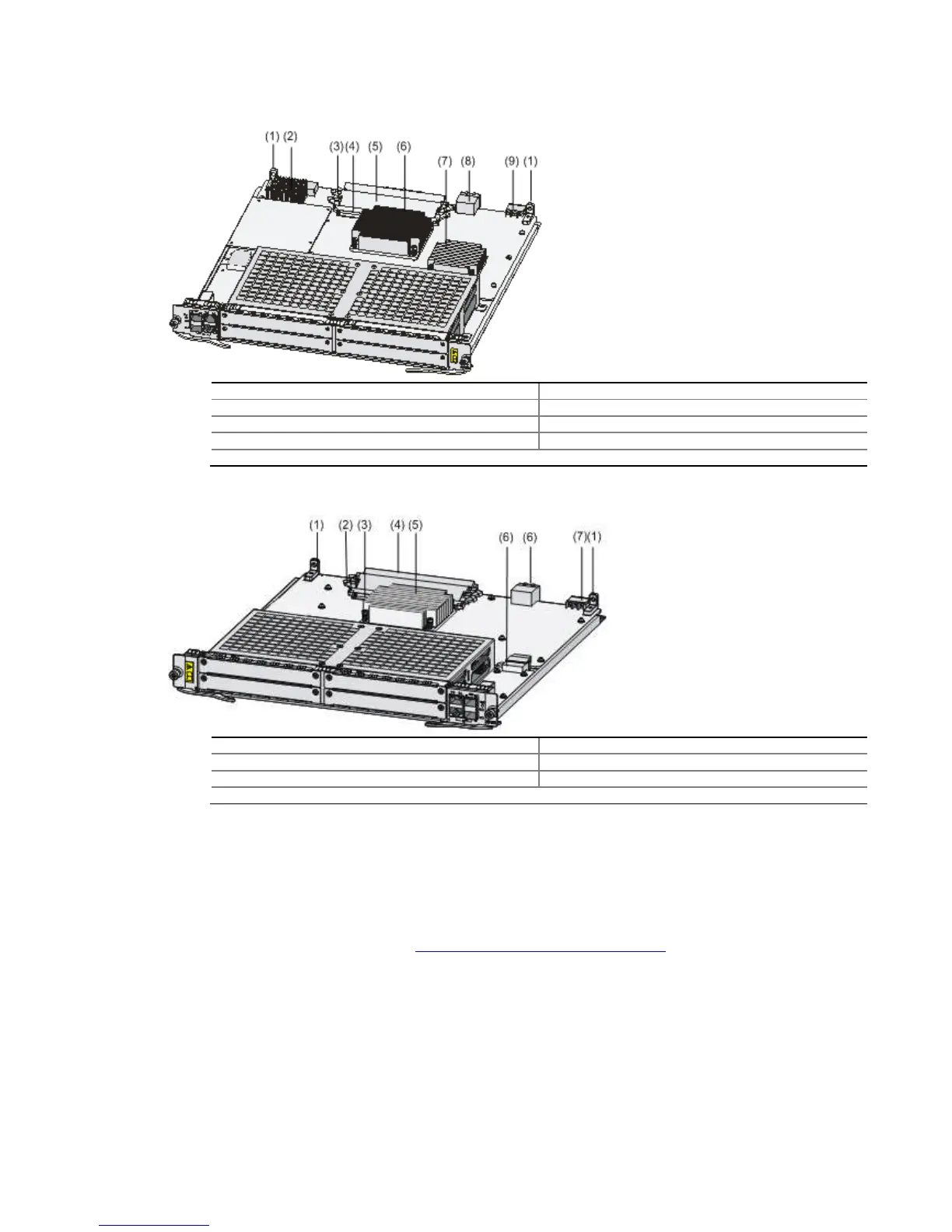
(1) Positioning holes
(3) Release latch
(5) Memory module
(7) Bridge heatsink 2
(9) Power connector
Figure 4-23
Interior structure of the
(5) CPU heatsink
(7) Power connector
Installing a FIP
The following describes how to install a FIP
Face the front panel of the router.
Locate the slot where you will install the FIP, and remove the blank panel from the position. For
how to remove a blank panel, refer to “
Gently push the FIP (with the components facing left) into the slot along the slide rails vertically
until positioning pins on the backplane are seated in the positioning holes, and then push the
ejector levers inward to lock the board in position.
-200
(2) Bridge heatsink 1
(6) CPU heatsink
(8) Bus connectors
Interior structure of the
(4) Memory module
(6) Bus connectors
The following describes how to install a FIP
-200. You can install a FIP-
Face the front panel of the router.
Locate the slot where you will install the FIP, and remove the blank panel from the position. For
how to remove a blank panel, refer to “
Installing and Removing a Blank Panel
Gently push the FIP (with the components facing left) into the slot along the slide rails vertically
until positioning pins on the backplane are seated in the positioning holes, and then push the
ejector levers inward to lock the board in position.
Locate the slot where you will install the FIP, and remove the blank panel from the position. For
Gently push the FIP (with the components facing left) into the slot along the slide rails vertically
until positioning pins on the backplane are seated in the positioning holes, and then push the