configured, the Insight Display verifies that there are no installation or configuration errors. The
Installation Wizard turns off the enclosure UID when the installation is complete.
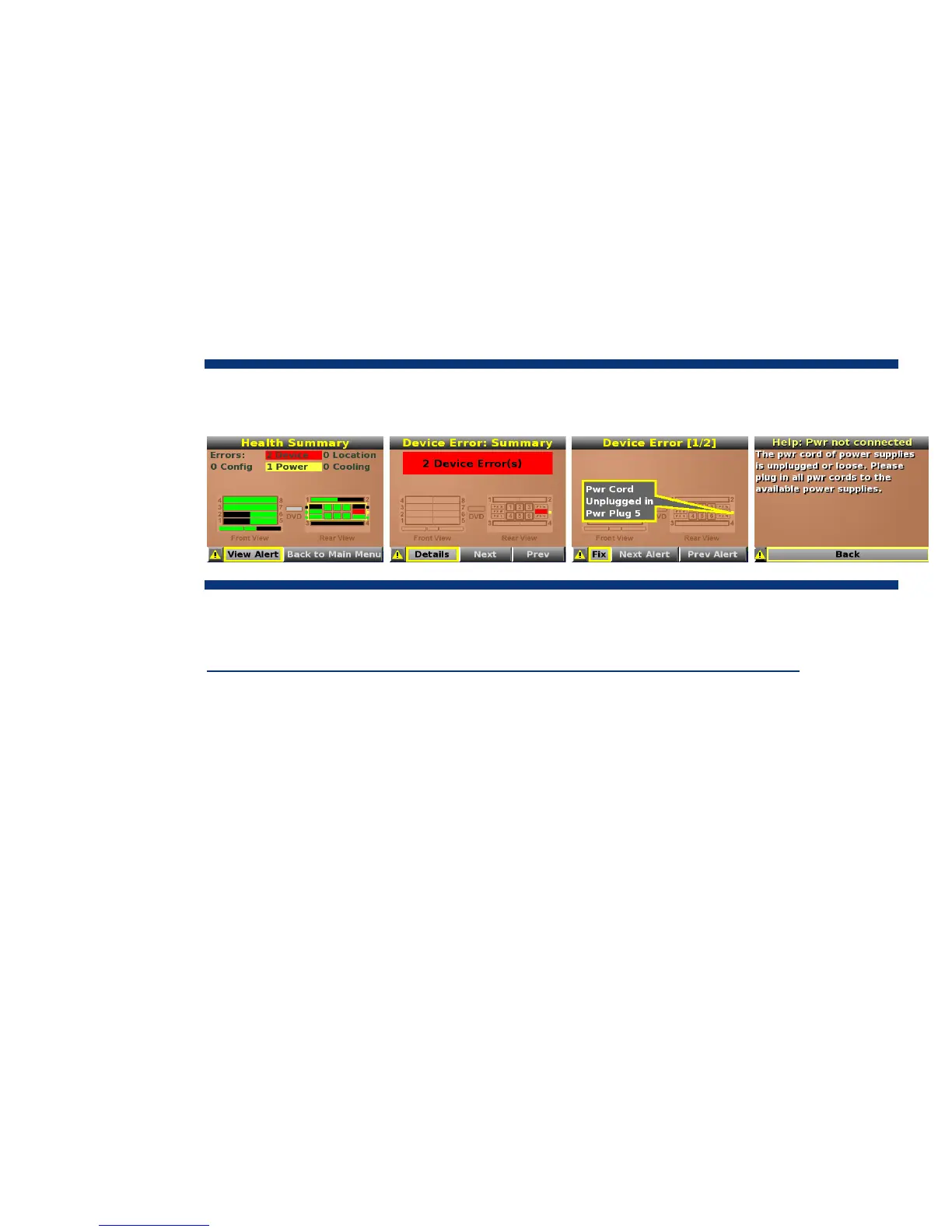
When an error or alert condition is detected, the Insight Display Health Summary screen displays the
total number of error conditions and their locations in the order of error severity (Figure 5). Failure
alerts (if any) are displayed first and then caution alerts are displayed. Providing this level of
diagnostic information for each enclosure dramatically shortens setup, repair, and troubleshooting
time.
For example, in Figure 5, the BladeSystem c-Class Insight Display diagnostic screen reports an error
in power supply bay 5. The device error reported on the Health Summary screen shows the power
supply in bay 5 as red. When the technician selects View Alert, the Device Error Summary screen
indicates the same condition. The Device Error detail in the third screen shows that the power supply
in bay 5 has failed. When the technician selects fix on the Device Error screen, suggestions for
corrective action appear.
Figure 5. BladeSystem c-Class Insight Display diagnostic screens indicating an error and suggested corrective
action
More information about the Insight Display is available in the technology brief entitled “Managing the
HP BladeSystem c-Class” at
http://h20000.www2.hp.com/bc/docs/support/SupportManual/c00814176/c00814176.pdf.
Onboard Administrator cabling
The standard Onboard Administrator module is preinstalled in a front-loading tray that also houses
the HP BladeSystem Insight Display. The Onboard Administrator module contains a serial connector
for connection to a PC with a null-modem RS232 serial cable. A USB connector is also available for
future USB connectivity. A separate rear-loading Onboard Administrator link module contains RJ-45
ports for enclosure link-up/link-down connectivity and Onboard Administrator network access
(Figure 6).
10