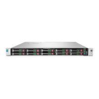
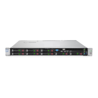
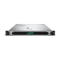
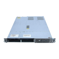
LEDs, Switches, and Jumpers
Table 5-1: Identifying the Front Panel LED Indicators
Item LED Status
1 Unit Identification
LED/button
Blue = Activated
Blinking = System remotely managed
Off = Deactivated
2 Internal health LED Red = System critical. Refer to system board LEDs to
identify component in critical state.
Amber = System degraded. Refer to system board LEDs to
identify component in degraded state.
Green = Normal
3 External health LED
(power supply)
Amber = Power redundancy failure
Green = Normal
4 NIC 1 link/activity LED Green = Network link
Blinking = Network link and activity
Off = No link to the network. If power is off, view the rear
panel RJ-45 LEDs.
5 NIC 2 link/activity LED Green = Network link
Blinking = Network link and activity
Off = No link to the network. If the power is off, view the rear
panel RJ-45 LEDs.
6 Power On/Standby
button/system
power LED
Amber = System shut down, but power still applied
Green = System on
Off = Power cord not attached or power supply failure
5-2 HP ProLiant DL360 Generation 3 Server Maintenance and Service Guide
 Loading...


