5–42 Maintenance and Service Guide
Removal and Replacement Procedures
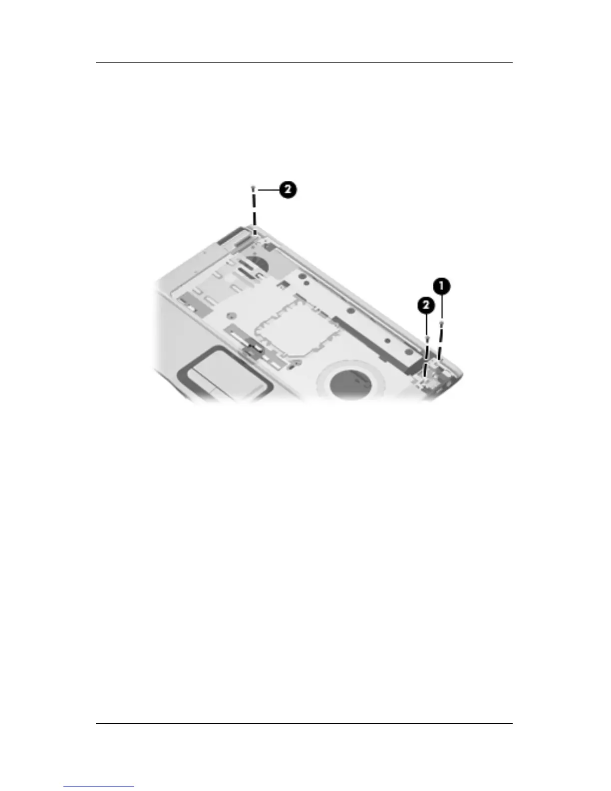
7. Remove the Phillips PM2.5×7.0 screw 1 that secures the top
cover support trim to the computer.
8. Remove the two Phillips PM2.5×7.0 screws 2 that secure the
top cover to the computer.
Removing the Top Cover Screws, Part 3