Removal and Replacement Procedures
Maintenance and Service Guide 5–53
1. Prepare the computer for disassembly (Section 5.3) and
remove the following components:
❏ Hard drive (Section 5.4)
❏ Optical drive (Section 5.9)
❏ Switch cover (Section 5.10)
❏ Keyboard (Section 5.11)
❏ Speaker assembly (Section 5.12)
❏ Display assembly (Section 5.14)
❏ Top cover (Section 5.15)
❏ Audio board (Section 5.16)
❏ USB/power connector board (Section 5.19)
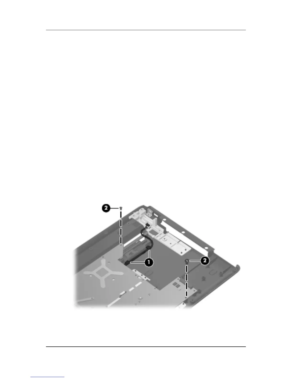
2. Remove the USB/power connector board cable 1 from the
clips in the base enclosure.
3. Remove the two Phillips PM2.5×5.0 screws 2 that secure the
system board to the base enclosure.
Removing the System Board Screws