6. Remove the service cover (see Service cover on page 34).
7. Remove the hard drive (see
Hard drive on page 34).
8. Remove the RTC battery (see RTC battery (see
RTC battery on page 49).
9. Remove the memory modules (see
Memory modules on page 37).
10. Remove the WLAN module (see
WLAN module on page 38).
11. Remove the optical drive (see
Optical drive on page 41).
12. Remove the base enclosure (see
Base enclosure on page 50).
13. Remove the fan (see
Fan on page 69).
14. Remove the system board (see
System board on page 70).
15. Remove the heat sink (see
Heat sink on page 72).
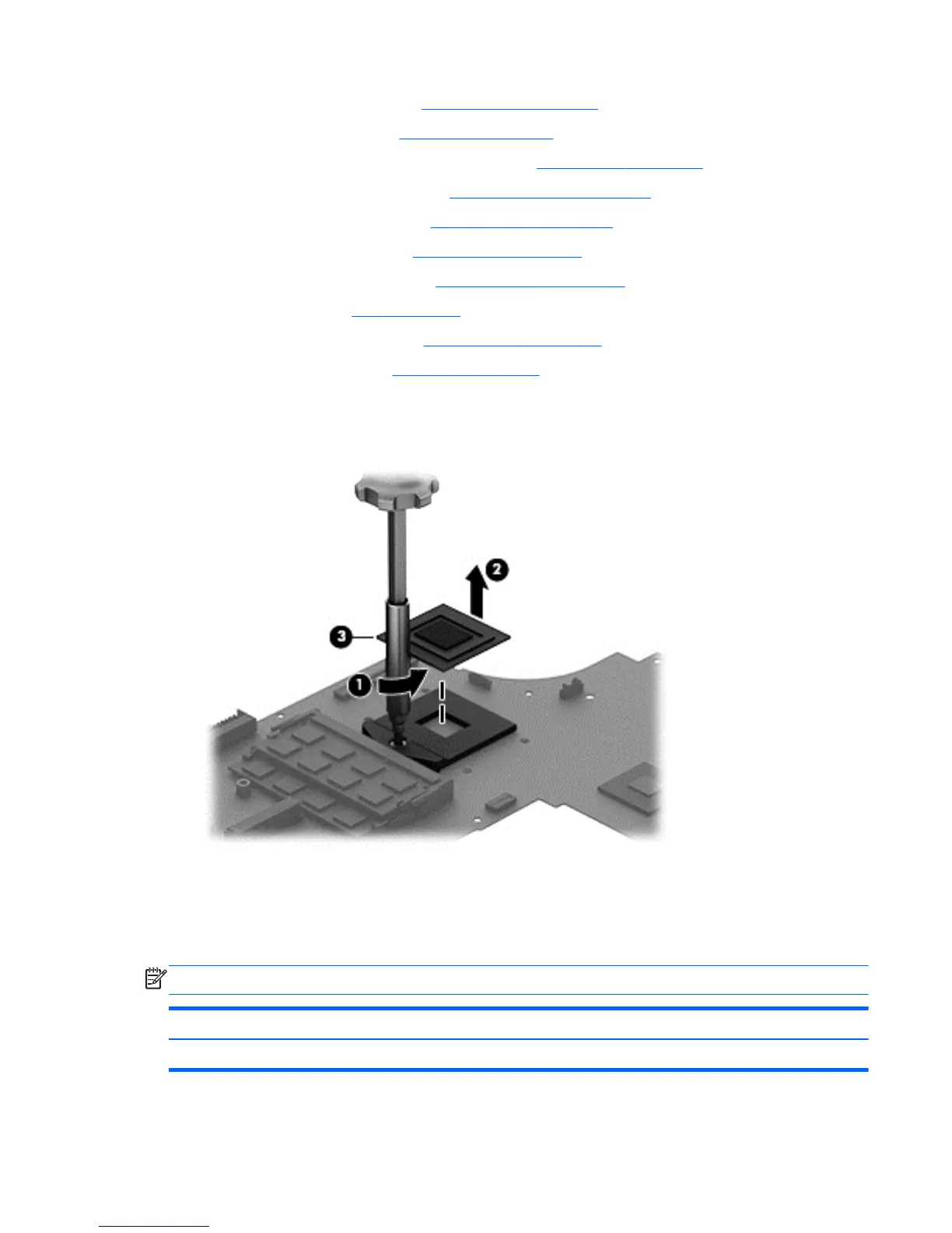
Remove the processor:
1. Use a Torx T8 screwdriver to unlock the processor by turning the screw counter-clockwise 1/2
turn (1).
2. Lift the processor (2) to remove it from the socket (3).
Reverse this procedure to install the processor.
Keyboard
NOTE: The keyboard spare part kit includes a keyboard cable.
For use in country or region: Spare part number: For use in country or region: Spare part number:
Backlit keyboard in black finish for non-touch models:
Component replacement procedures 75