10. Remove the WLAN module (see WLAN module on page 38).
11. Remove the optical drive (see
Optical drive on page 41).
12. Remove the base enclosure (see
Base enclosure on page 50).
13. Remove the fan (see
Fan on page 69).
14. Remove the system board (see
System board on page 70).
15. Remove the keyboard (see
Keyboard on page 75).
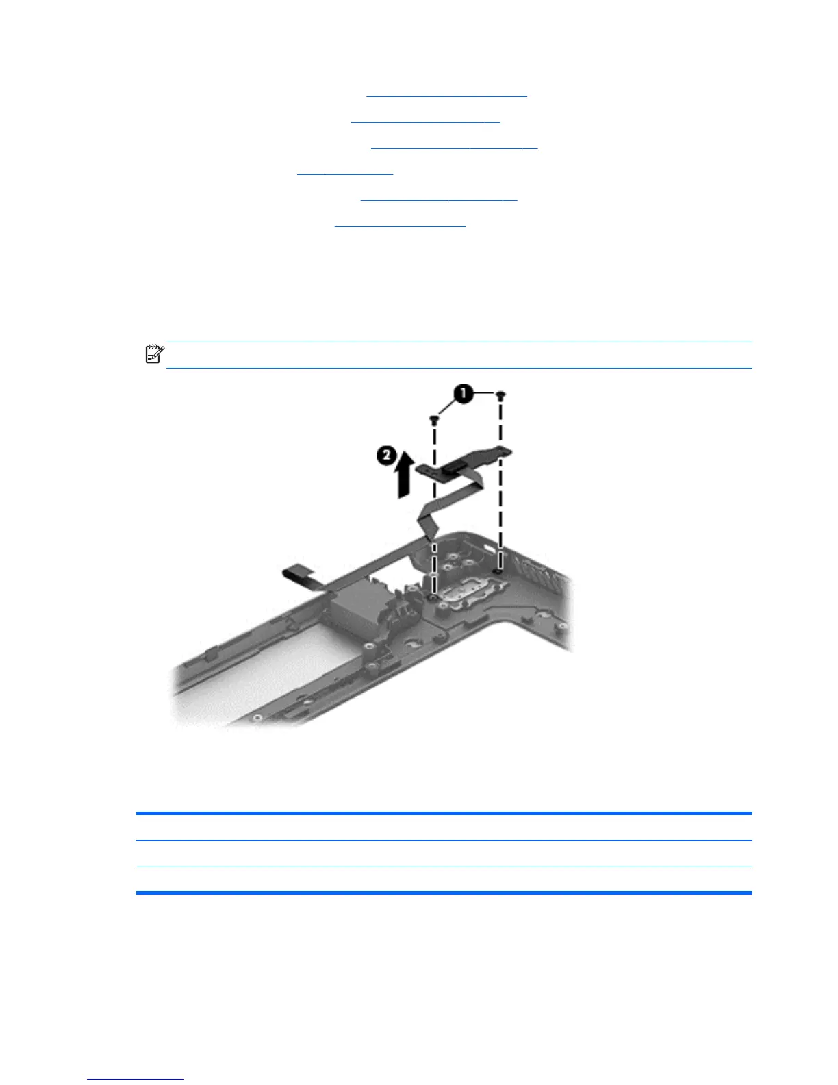
Remove the Power button board and cable:
1. Turn the top cover upside down, with the back edge toward you.
2. Remove the 2 Phillips PM 2.0x3x0 screws securing the Power button board to the top cover (1).
3. Remove the Power button board (2).
NOTE: The Power button board's cable is attached to the board.
Reverse this procedure to install the Power button board.
TouchPad module
Description Spare part number
TouchPad module for non-touch models 720253-001
TouchPad module for touch models 720230-001
80 Chapter 6 Removal and replacement procedures for Authorized Service Provider parts