10
FCF mode
An FCF switch encapsulates FC frames in Ethernet frames and uses FCoE virtual links to simulate physical
FC links. In this way, an FCF switch provides standard FC switching capabilities and features on a
lossless Ethernet network.
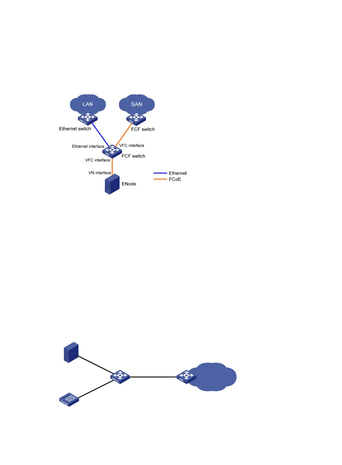
Figure 10 FCF network diagram
In an FCoE environment as shown in Figure 10, an FCF switch can perform the following operations:
• Connect to an Ethernet switch through an Ethernet interface.
• Connect to an FCF switch through a VFC interface.
• Connect to an ENode or FCF switch through a VFC interface. In this case, an FCoE virtual link is
established between the Ethernet interfaces of the two devices. The FCoE virtual link provides
communication over a lossless Ethernet network. The peer end of the FCoE virtual link can be a VN
interface or a VFC interface.
Each FCF switch is assigned a domain ID. Each FC SAN supports a maximum number of 239 domain IDs,
so an FC SAN cannot have more than 239 switches.
NPV mode
An FC SAN needs a large number of edge switches that are connected directly to nodes. NPV switches
are developed to expand the number of switches in an FC SAN.
Figure 11 NPV network diagram
NP_Port F_Port
F_Port
F_Port
N_Port
N_Port
Core switchNPV switch
Fabric
Server
Disk device
 Loading...


