38
Planning IRF topology and connections
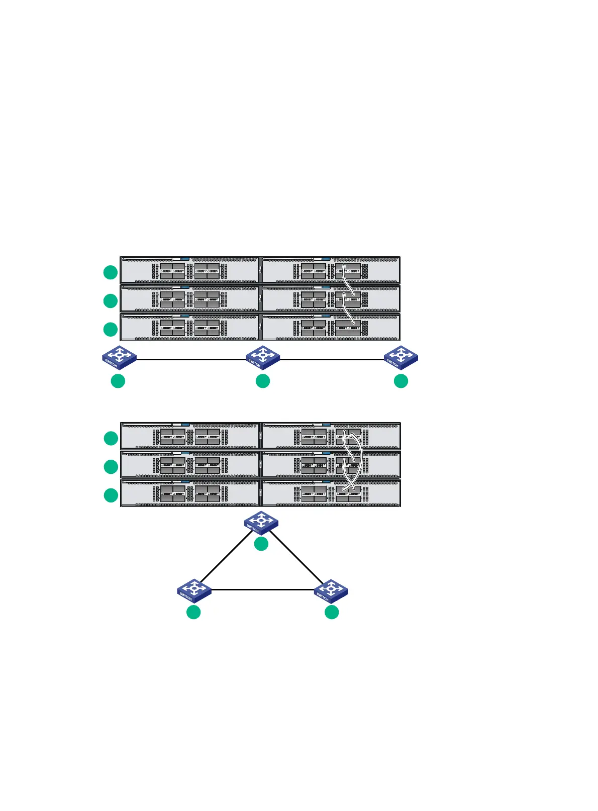
You can create an IRF fabric in daisy chain topology, or more reliably, ring topology. In ring topology,
the failure of one IRF link does not cause the IRF fabric to split as in daisy chain topology. Rather, the
IRF fabric changes to a daisy chain topology without interrupting network services.
You connect the IRF member switches through IRF ports, the logical interfaces for the connections
between IRF member switches. Each IRF member switch has two IRF ports: IRF-port 1 and IRF-port
2. To use an IRF port, you must bind at least one physical port to it.
When connecting two neighboring IRF member switches, you must connect the physical ports of
IRF-port 1 on one switch to the physical ports of IRF-port 2 on the other switch.
The IRF port connections in the two figures are for illustration only, and more connection methods
are available.
Figure 45 IRF fabric in daisy chain topology
Figure 46 IRF fabric in ring topology
You can provide the following IRF physical connections between HPE FlexFabric 5930 switches:
• 10-GE IRF physical connection by connecting 1/10-GE Ethernet ports or SFP+ ports.
• 40-GE IRF physical connection by connecting QSFP+ ports.
• IRF physical connection by using a 40G QSFP+ to SFP+ network cable to connect a QSFP+
port and four SFP+ ports.
You can bind several ports to an IRF port for increased bandwidth and availability.
1
2
3
IRF-port1IRF-port1
IRF-port2 IRF-port2
1 2 3
IRF-port1
IRF-port2
IRF-port1
IRF-port1
IRF-port2
IRF-port2
1
2
3
1
2 3
 Loading...