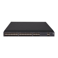
63
Figure 63 Airflow through the HPE 5930-32 QSFP+/HPE 5930-32 QSFP+ TAA chassis (with
the LSWM1HFANSCB fan trays)
IMPORTANT:
The chassis and the power supplies use separate air aisles. Make sure both aisles are not blocked.
HPE 5930-4Slot/HPE 5930-4Slot TAA cooling
system
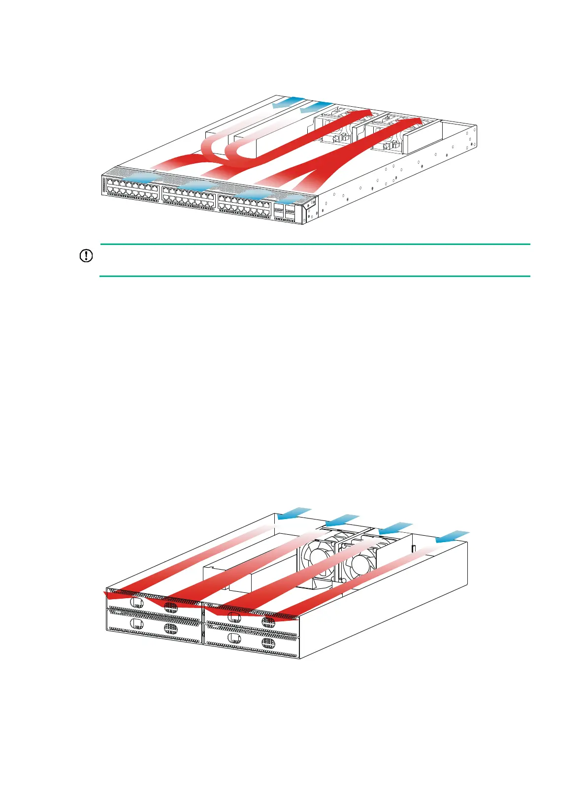
You must install two fan trays of the same model for the HPE 5930-4Slot/HPE 5930-4Slot TAA switch:
LSWM1BFANSC or LSWM1BFANSCB.
• When LSWM1BFANSC fan trays are used, cool air flows in through the air vents in the fan tray
panel and the power supply panels, circulates through the chassis and the power supplies, and
exhausts at the network port side, as shown in Figure 64.
• Whe
n LSWM1BFANSCB fan trays are used, cool air flows in through the air vents in the
network port-side panel and the power supply panels, circulates through the chassis and the
power supplies, and exhausts through the air vents in the fan tray panels, as shown in Figure
65.
Figure 64
Airflow through the HPE 5930-4Slot/HPE 5930-4Slot TAA chassis (with the
LSWM1BFANSC fan trays)
 Loading...