2-2 Removal and Replacement HP Omnibook 500
Disassembly Flowchart
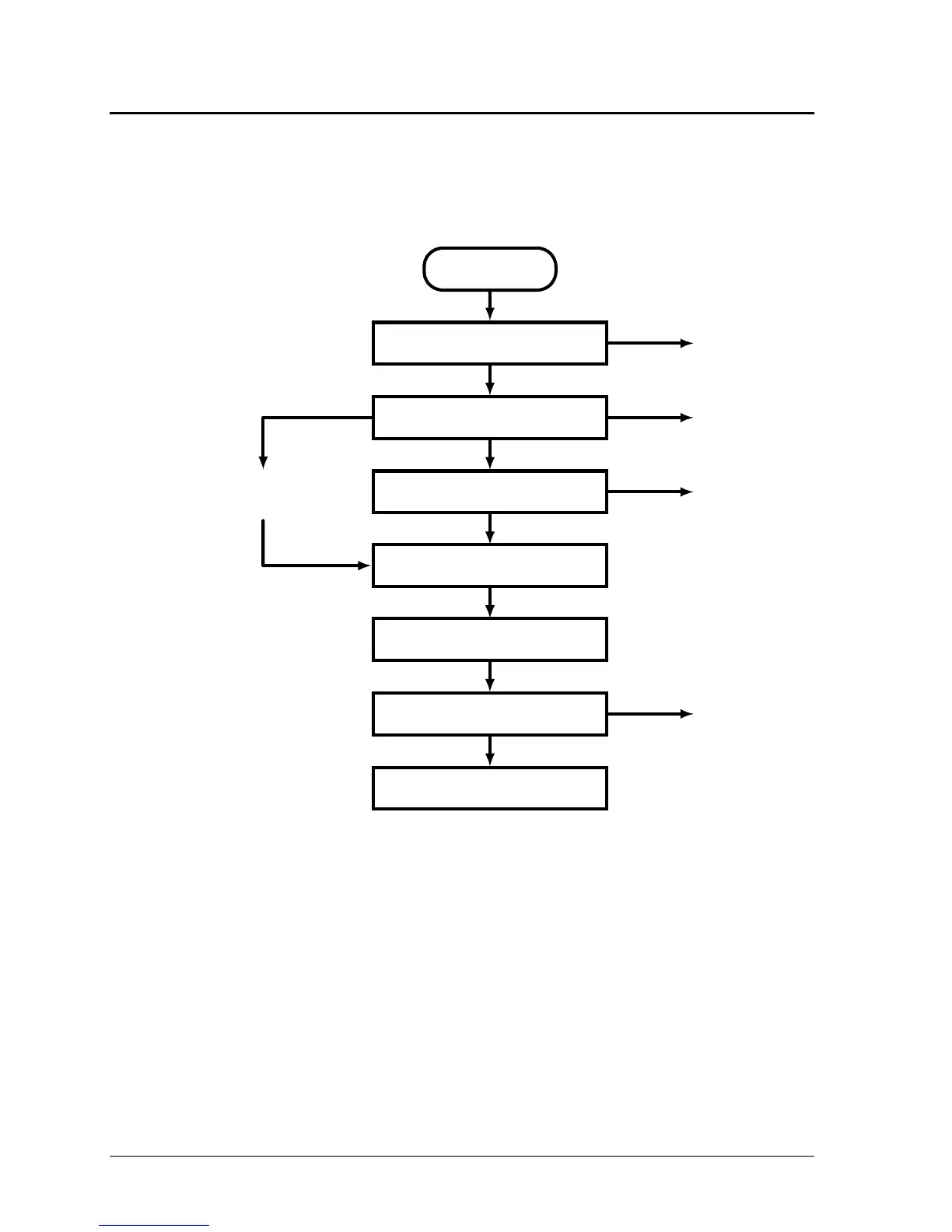
The following diagram shows the general “path” you will use in disassembling the computer to access
components.
* Also remove these components when removing the motherboard or bottom case.
‡ Also remove this component when replacing the top case.
Figure 2-1. Disassembly Flow
Start
Main battery, AC adapter
Power button panel
Keyboard
Display assembly
Top case
Motherboard or
bottom case
•
Hard drive/LED flex cable
• Backup battery
• Audio/PCMCIA panel
• Hard drive guide
• Mini-PCI panel
• Mini-PCI card
• Speaker
• System SDRAM module*
• Heatsink/fan*
• Switchboard PCA*
If removing only
the display
• Expansion SDRAM module*
• Hard disk drive*
Wireless models only:
Switchboard PCA
 Loading...