HP OmniBook 6000 Removal and Replacement 2-19
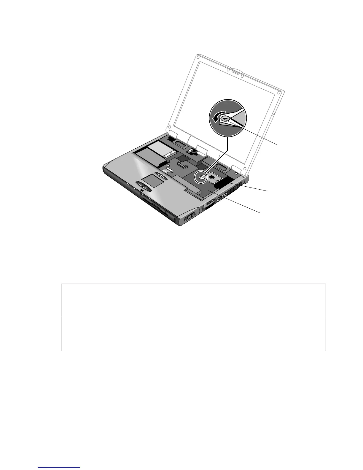
Figure 2-14. Removing the CPU Module
Reassembly Notes
• Carefully insert the CPU module into the motherboard, and turn the lock screw one-half turn
clockwise to secure the CPU module.
• The CPU module is keyed for installation, and can only be inserted one way.
Note: Setting the SpeedStep Power Level DIP Switches
Whenever you install a new CPU, you must make sure the SpeedStep power level DIP switches
are set correctly for that CPU. These switches are located on the motherboard next to the volume
PCA, and control the power level to the CPU in the SpeedStep high-speed mode.
The settings to use depend on the “Q” batch number printed on the upper surface of the CPU.
The following settings are for batch number Q49:
1: ON 2: ON 3: ON 4: OFF 5: ON 6: not used
For other batch numbers, see the appropriate Service Note.
CPU module
lock screw
CPU module
Power-level
DIP switches
 Loading...