Home
HP
Laptop
Pavilion ze4200 - Notebook PC
Page 92 (Figure 2-15. Removing the CD;DVD Drive)
HP Pavilion ze4200 - Notebook PC - Figure 2-15. Removing the CD;DVD Drive
188 pages
Manual
To Next Page
To Next Page
To Previous Page
To Previous Page
Loading...
Figure 2-15. Removing the CD/DVD Driv
e
HP Pavilion 4300, 4200, and 4100, HP nx9005 and nx9000,
Compaq Evo Notebook N1050 and 1010, and Compaq Presario 2100 and 1100 Models
Service Manual
Removal and Replacement
2-21
91
93
Table of Contents
Main Page
Table of Contents
3
Table 1-1. Notebook Products
7
Table 1-2. Product Comparisons
49
Features
54
Figure 1-1. Front View
54
Figure 1-2. Back View
55
Figure 1-3. Bottom View
56
Figure 1-4. Front View
57
Figure 1-5. Back View
58
Figure 1-6. Bottom View
59
Operation
60
Table 1-3. Activating Power Modes
60
Table 1-4. Main Status Lights (Front of Notebook)
61
Table 1-5. Keyboard Status Lights
61
Table 1-6. Fn Hot Keys
62
Figure 1-7. Resetting the Notebook
63
Specifications
64
Table 1-7. Specifications
64
Table 1-8. Accessories
68
Figure 1-8. Replaceable Module Diagram
70
Internal Design
70
Table 1-9. Functional Structure Description
71
Removal and Replacement
72
Table 2-1. Removal Cross-Reference
72
Table 2-2. Required Equipment
73
Table 2-3. Recommended Screw Torque Values
73
Disassembly Flowchart
74
Figure 2-1. Disassembly Flow
74
Figure 2-2. Removing the Battery
75
Removing the Battery
75
Figure 2-3. Removing an SDRAM Module
76
Removing a SDRAM Module
76
Figure 2-4. Removing an SDRAM Module
77
Figure 2-5. Removing the Mini-PCI Card
78
Removing the Wireless LAN Mini-PCI Card
78
Figure 2-6. Removing the Mini-PCI Card
79
Figure 2-7. Removing the Hard Disk Drive
80
Removing the Hard Disk Drive
80
Figure 2-8. Removing the Hard Disk Drive Tray
81
Replacing Small Parts
82
Table 2-4. Replacing Small Parts
82
Removing the Keyboard Cover
83
Figure 2-9. Removing the Keyboard Cover
84
Figure 2-10. Disconnecting the Speaker Cable
85
Figure 2-11. Removing the Speaker Assembly
86
Removing the Speaker Assembly
86
Removing the Keyboard
87
Figure 2-12. Removing the Keyboard
88
Figure 2-13. Removing the Switchboard PCA
89
Figure 2-14. Removing the Switchboard PCA
90
Removing the Switchboard PCA
90
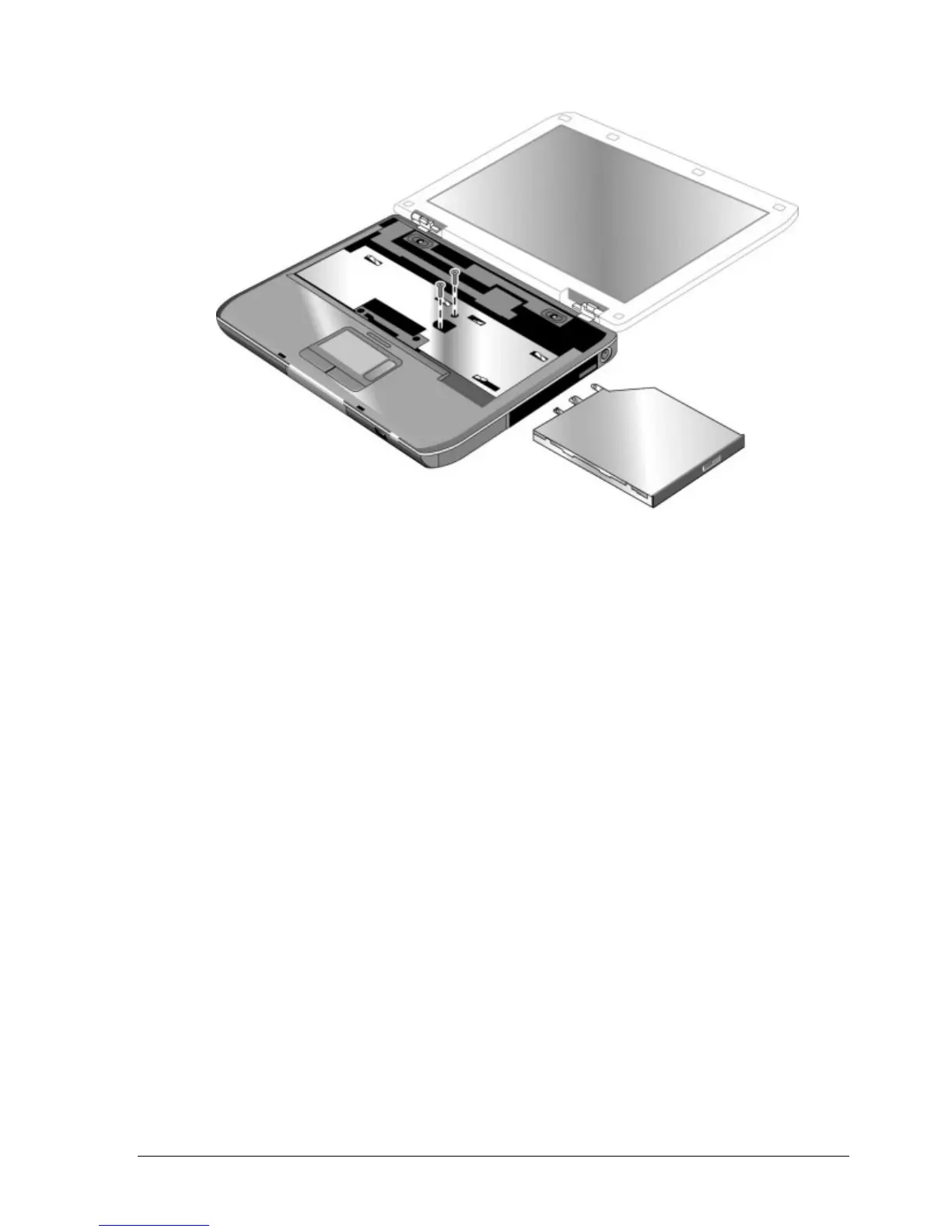
Removing the CD/DVD Drive
91
Figure 2-15. Removing the CD/DVD Drive
92
Figure 2-16. Removing the CD/DVD Drive
93
Removing the Display Assembly
94
Figure 2-17. Removing the Display Assembly
95
Removing the Top Case
97
Figure 2-18. Removing the Top Case
98
Figure 2-19. Removing the Top Case Screws
100
Figure 2-20. Removing the Top Case Screws
101
Figure 2-21. Removing the Top Case
102
Removing the Floppy Drive
103
Figure 2-22. Removing the Floppy Drive
104
Figure 2-23. Removing the Floppy Drive
106
Removing the Infrared (I/R) PCA
107
Figure 2-24. Removing the I/R PCA
108
Removing the Audio PCA
109
Figure 2-25. Removing the Audio PCA
110
Figure 2-26. Removing the Heat Sink (with Fan)
111
Removing the Heat Sink (with Fan)
111
Figure 2-27. Removing the Heat Sink (with Fan)
113
Removing the CPU Module
115
Figure 2-28. Removing the CPU Module
116
Figure 2-29. Removing the CPU Module
118
Removing the RJ11/1394 Connector Module
119
Figure 2-30. Removing the RJ11/1394 Connector Module
120
Removing the Motherboard
121
Figure 2-31. Removing the Motherboard
122
Removal Procedure
123
Figure 2-32. Removing the Hard Disk Drive Guide
124
Figure 2-33. Disconnecting the Motherboard Cables
125
Figure 2-34. Removing the Motherboard
127
Figure 2-35. Example of Serial Number Label
130
Replacing Components on a Bottom Case
130
Figure 2-36. Replacing the Antennas
131
Figure 2-37. Removing a PCMCIA Door
131
Repairing the BIOS IC
132
Figure 2-38. Boot-Block Jumper
133
Removing Other Components
134
Table 2-5. Removing Components
134
Troubleshooting and Diagnostics
136
Support by Authorized Service Providers
136
Table 3-1. ASP Support Options
136
Troubleshooting
137
Figure 3-1. Basic Troubleshooting Steps
137
Checking for Customer Abuse
138
Troubleshooting the Problem
138
Verifying the Repair
139
Table 3-2. Scope of Diagnostic Tools
140
Table 3-3. Troubleshooting Suggestions
141
Diagnostic Tools
153
Table 3-4. POST Terminal-Error Beep Codes
155
Table 3-5. POST Messages
158
Table 3-6. Sycard Pcctest Commands
160
Bios Setup Utility
161
Table 3-7. BIOS Setup Menus and Parameters
162
Replaceable Parts
164
Figure 4-1. Exploded View
165
Figure 4-2. Exploded View
166
Table 4-1. Replaceable Parts
167
Table 4-1. Replaceable Parts
168
Table 4-2. Accessory Replaceable Parts
175
Table 4-3. Part Number Reference
176
Reference Information
185
Password Removal Policy
185
Hewlett-Packard Display Quality Statement
186
Table 5-1. LCD Guidelines
187
Service Notes and Obsolete Parts
188
Related product manuals
HP Pavilion ze4300 - Notebook PC
8 pages
HP Pavilion zd7000 - Notebook PC
67 pages
HP Pavilion zv5000 - Notebook PC
56 pages
HP Pavilion Notebook PC
74 pages
HP Pavilion Notebook PC 17
5 pages
HP Pavilion 14 Notebook PC
95 pages
HP Pavilion n5000 - Notebook PC
153 pages
Pavilion dv9000 - Entertainment Notebook PC
38 pages
Pavilion dv9500 - Entertainment Notebook PC
30 pages
Pavilion dv3000 - Entertainment Notebook PC
48 pages
Pavilion HDX9000 - Entertainment Notebook PC
18 pages
Pavilion dv2-1000 - Entertainment Notebook PC
37 pages