2-16
Installing the Switch 2650
Installation Procedures
Installing the Switch 2650
6. Connect the Network Cables
Connect the network cables, described under “Cabling Infrastructure” (page
2-4), from the network devices or your patch panels to the fixed RJ-45 ports
on the switch or to any mini-GBICs you have installed in the switch.
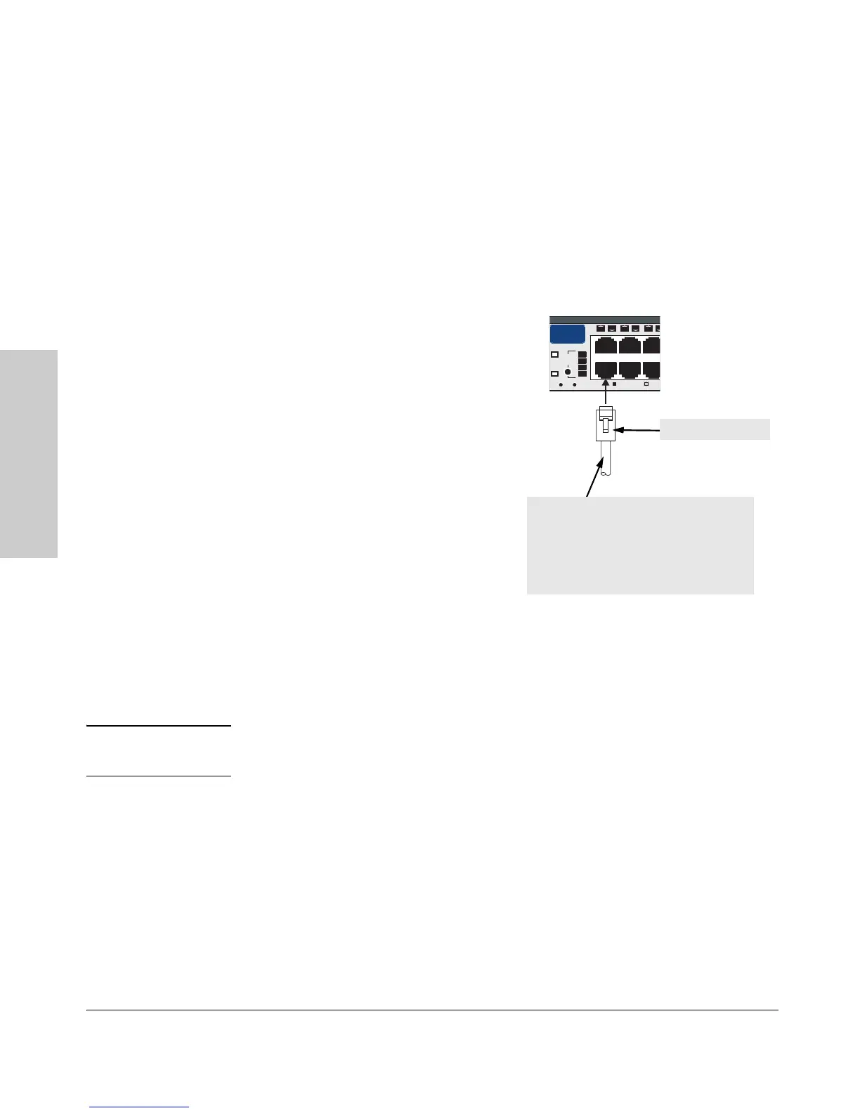
Using the RJ-45 Connectors
To co nnect:
Push the RJ-45 plug into the RJ-45
jack until the tab on the plug clicks
into place. When power is on for the
switch and for the connected device,
the Link LED for the port should light
to confirm a powered-on device (for
example, an end node) is at the other
end of the cable.
If the Link LED does not go on when
the network cable is connected to the
port, see “Diagnosing With the LEDs”
in chapter 4, “Troubleshooting”.
To disconnect:
Press the small tab on the plug and
pull the plug out of the jack.
Connecting Cables to mini-GBICs
Note The mini-GBIC slots are shared with the two 10/100/1000Base-T RJ-45 ports.
If a mini-GBIC is installed in a slot, the associated RJ-45 port is disabled.
If you have any mini-GBICs installed in the switch, the type of network
connections you will need to use depends on the type of mini-GBICs you have
installed. See the table on page 2-5, and appendix B, “Switch Ports and
Network Cables”, for the mini-GBIC cabling information.
For mini-GBICs ports, and in general for all the switch ports, when a network
cable from an active network device is connected to the port, the port LED
for that port should go on. If the port LED does not go on when the network
cable is connected to the port, see “Diagnosing With the LEDs” in chapter 4,
“Troubleshooting”.
Port
LED
View
Self
Test
Clear
eset
Fan
Status
4
5

 Loading...