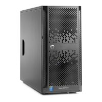
-1 Cable connection
From To # of pins
Power supply, P1 System board, J39 24
Power supply, P2 System board, J14 4
Power supply, P3 System board, J37 8
Power supply, RPS System board, J25 16
Power supply , P8, 9, 14, 15 ATX drives and/or hot-plug HDD backplane 4
Power supply, P4-7, 10-13 SATA drives 15
System Fan 1 System board, J54 6
System Fan 2 System board, J44 6
System Fan 3
System board, J38 6
System Fan 4
System board, J4 6
Front USB 2.0 ports System board, J30 10
System board SATA1 SATA hard drive #1 [1], J40 7
System board SATA2 SATA hard drive #2 [1], J51 7
System board SATA3 SATA hard drive #3 [1], J52 7
System board SATA4 SATA hard drive #4 [1], J41 7
System board SATA5 SATA optical drive #1, J29 7
System board SATA6 SATA optical drive #2, J26 7
NOTE:
[1] For systems with hot-pluggable hard disk drives, hard drives #1-4 are terminated into one connector that attaches to the
hot-plug SAS/SA T A module.
 Loading...


