Table 1-2 Identifying the front panel components
Front panel components
(1) LCD screen
(2) Remote host status LED
(3) Remote System Controller status LED
(4) Network status LED
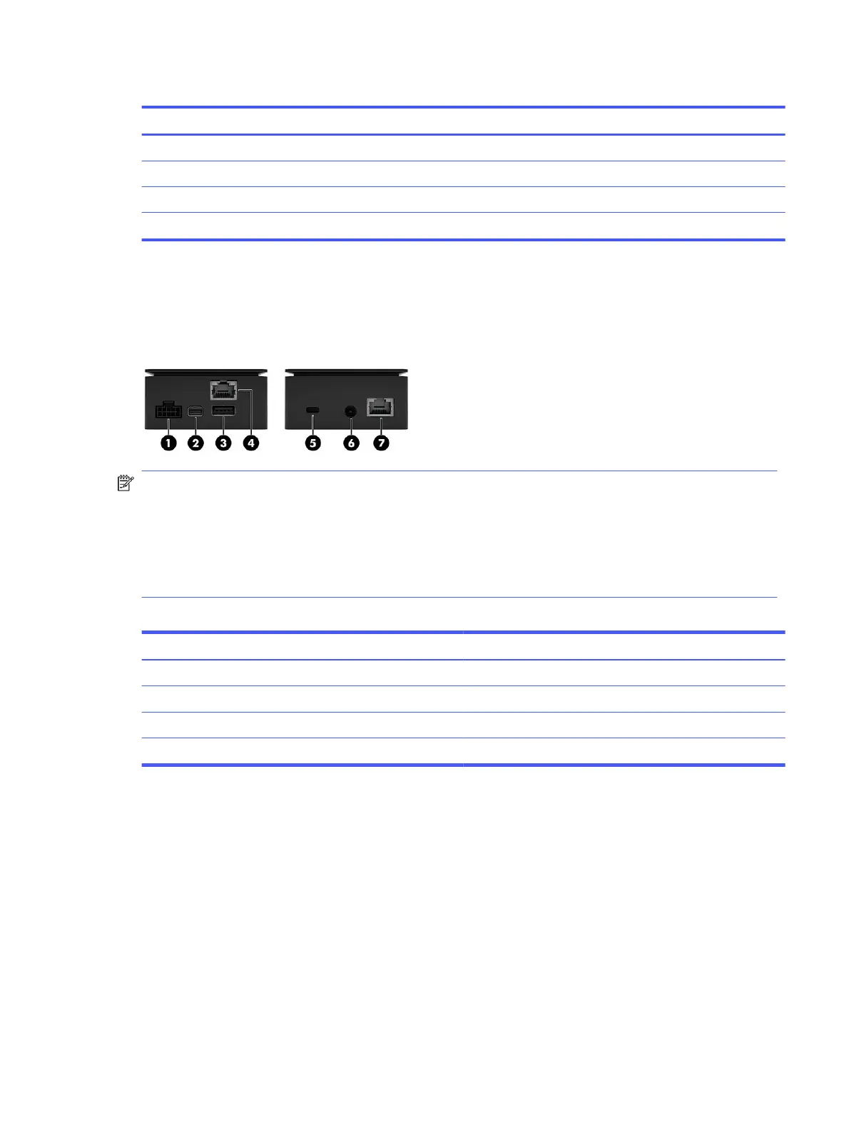
Left and right panel components (external)
To identify the left and right panel components for the HP Remote System Controller, use this illustration
and table.
NOTE: *If you install the HP Z4/Z6/Z8 G4 / ZCentral 4R Remote System Controller Cable Adapter
(7K6E5AA), the HP Remote System Controller or HP Integrated Remote System Controller redirects
power from the front USB ports on the workstation to power the Remote System Controller in all host
states. In this situation, bus-powered devices such as keyboards, mice, USB thumb drives, and other
peripherals cannot be powered when they are installed in the front USB ports. Powering the HP Remote
System Controller or HP Integrated Remote System Controller in all host states requires an update to
the latest available BIOS for the ZCentral 4R, Z4G4, Z6G4, and Z8G4 platforms.
Table 1-3
Identifying the left and right panel components
Left panel components Right panel components
(1) 10-pin cable connector (5) Security cable slot
(2) Mini DisplayPort™ connector (6) Power cable connector
(3) USB 5 Gbps port* (7) Network jack
(4) RJ-45 (network) jack
Front components (internal)
To identify the front panel components for the HP Integrated Remote System Controller, use this
illustration and table.
Left and right panel components (external)
3