Shenzhen Hpmont Technology Co., Ltd Chapter 4 Electrical Installation
HD5L Series Controller User Manual ―27―
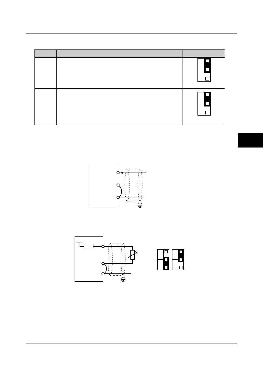
4.5.2 I/O Card Wire Jumper Description
Table 4-6 Wire jumper function and setting description on the I/O card
Jumper Function and setting description Factory setting
CN2
AI4 analogue input channel can select voltage or current signal.
When pin 1 and pin 2 of the CN2 are short-circuited, AI4 channel
inputs voltage signal;
When pin 2 and pin 3 of the CN2 are short-circuited, AI4 channel
inputs current signal.
CN3
AI4 analogue input channel can select thermistor.
When pin 1 and pin 2 of the CN3 are short-circuited, AI4 channel is
for the user reference analogue input;
When pin 2 and pin 3 of the CN3 are short-circuited, AI4 channel is
for the motor over-heating detection signal input via the external
connected thermistor.
4.5.3 I/O Card Terminal Connection
Analogue input terminal connection
When the AI4 is used as the user reference analogue input terminal, the connection is shown as
Figure 4-18 and the AI4+ is as analogue input.
Figure 4-18 AI4 as the analogue input terminal
When the AI4 is used as the motor over-heating detection signal input terminal, the connection is
shown as Figure 4-19. The motor stator coil built-in thermistor to access the analogue input and it
should be correctly set the wire jumper.
Figure 4-19 AI4 as the over-heating signal detection input terminal
Digital input terminal connection
The digital input terminals (DI7
-
DI12) of I/O card and the digital input terminals (DI1
-
DI6) of
control board have the same connection method. Please refer to 4.4.4 Control Terminal
Connection for details.
PE
AI4-
GND
AI4+ Analogueinput
-10-+10V or
0-20mA
I/O card
AI4-
GND
AI4+
Wire jumper setting
+5V
10k
CN2
1
3
V
I
CN3
1
3
V
R
PE
I/O card
Thermistor
4
 Loading...
