lp-505 Rev. 000 Rel. 015 Date 1.7.20
23
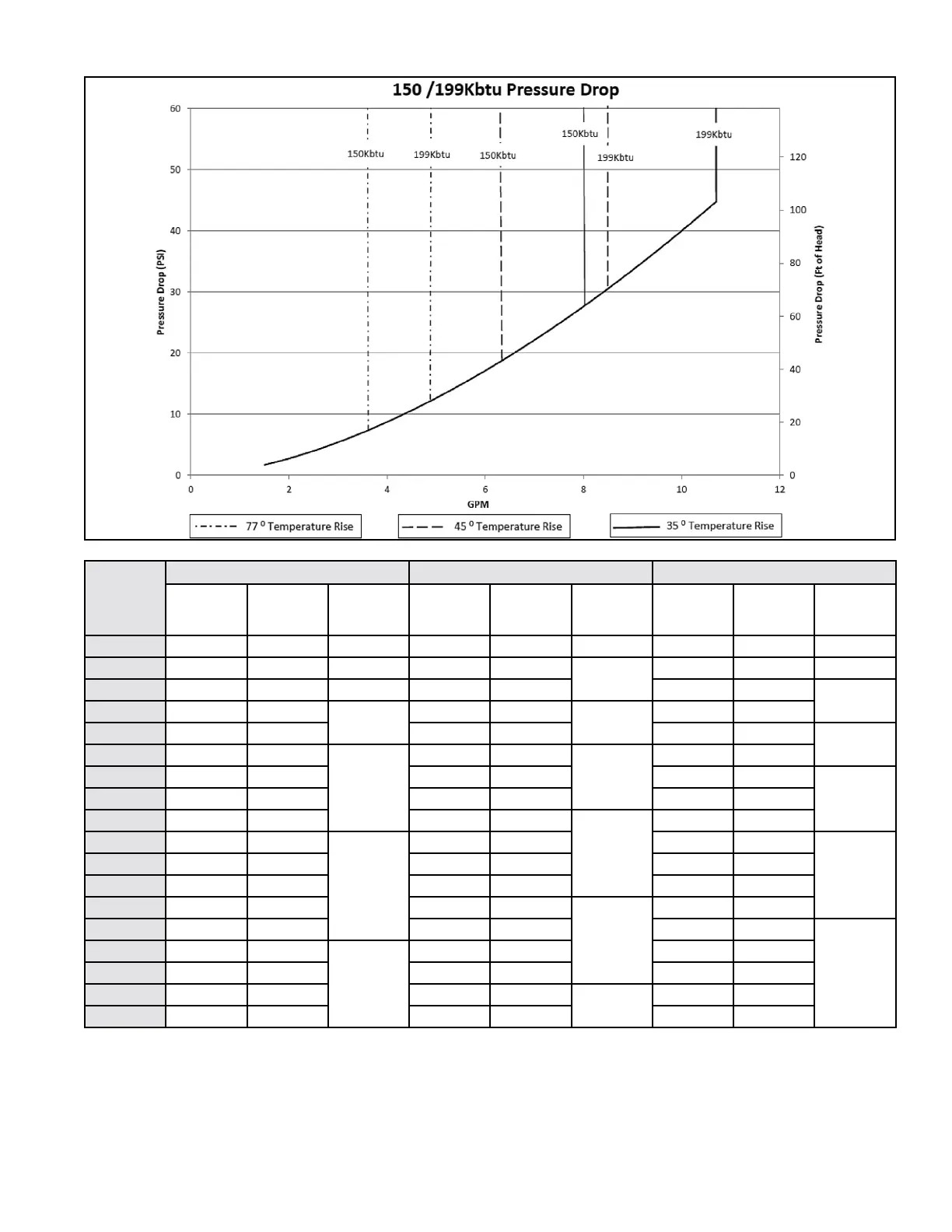
Figure 16 - Pressure Drop through the Heat Exchanger
F. Circulator Sizing
NOTE: The above pipe sizes are recommended based on water velocity of 5 ft/s and a maximum water temperature of 140
o
F.
Number of
Units
∆T = 77
o
F ∆T = 45
o
F ∆T = 35
o
F
Flow Rate
(GPM)
Water
Velocity
(ft/s)
Pipe Dia.
(In.)
Flow Rate
(GPM)
Water
Velocity
(ft/s)
Pipe Dia.
(In.)
Flow Rate
(GPM)
Water
Velocity
(ft/s)
Pipe Dia.
(In.)
1 5 3.75 3/4 9 3.61 1 11 4.64 1
2 10 4.22 1 18 3.21
1 1/2
23 4.13 1 1/2
3 16 4.05 1 1/4 27 4.82 34 3.48
2
4 21 3.75
1 1/2
35 3.61
2
45 4.64
5 26 4.69 44 4.52 57 3.72
2 1/2
6 31 3.17
2
53 3.47
2 1/2
68 4.46
7 36 3.69 62 4.05 80 3.61
38 41 4.22 71 4.62 91 4.13
9 47 4.75 80 3.61
3
102 4.64
10 52 3.38
2 1/2
88 4.01 114 3.79
3 1/2
11 57 3.72 97 4.42 125 4.17
12 62 4.05 106 4.82 136 4.55
13 67 4.39 115 3.83
3 1/2
148 4.93
14 72 4.73 124 4.13 159 4.06
4
15 78 3.52
3
133 4.42 171 4.35
16 83 3.75 142 4.72 182 4.64
17 88 3.99 150 3.84
4
193 4.94
18 93 4.22 159 4.06 205 5.23
Table 13 - Recommended Water Pipe Size
G. Pressure Relief Valve
An external pressure relief valve must be installed on this water heater. When installing, observe the following guidelines. Failure to comply
with these guidelines can result in substantial property damage, personal injury, or death.
This water heater must be provided with an approved 150 psi, ¾” ASME HV Valve that must be installed on the DHW outlet line. The 150 psi
Pressure Relief Valve must be installed on the DHW outlet line to ensure a compliant installation and safe operation.
This water heater has a high-temperature shut-o switch built in as a standard safety feature. Therefore, a “pressure only” relief valve is
 Loading...